
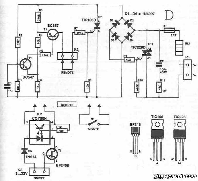
Isolation and zero voltage switching logic

The described circuits implement zero voltage switching, a technique that enhances the efficiency and reliability of thyristor control in power applications. The circuits are designed to work with full wave bridge rectifiers or in an antiparallel configuration, allowing for effective full wave control of the load.
In operation, when the AC voltage is within the range of 0 to 7 V and an appropriate input signal is detected, the silicon-controlled rectifier (SCR) is triggered into the 'on' state. This is achieved through the application of a gate pulse that activates the SCR, allowing current to flow through the load. The SCR remains in this conducting state until the current through it drops below a certain threshold, typically at the next zero crossing of the AC waveform.
Conversely, if the AC voltage exceeds 7 V and an input signal is applied, the circuit behavior changes. The transistor Q1 is turned on, which prevents the SCR from conducting. This is due to the biasing of Q1, which effectively holds the SCR in the 'off' state, thereby ensuring that no current flows through the relay until the AC voltage returns to zero. This feature is crucial for preventing unintended triggering of the SCR during high voltage conditions, thus providing a protective function and ensuring stable operation of the circuit.
These circuits are particularly useful in applications where precise control of AC loads is required, such as in light dimmers, motor speed controllers, and other power electronics applications where efficiency and reliability are paramount. The zero voltage switching technique minimizes electrical noise and stress on the components, enhancing the longevity and performance of the overall system.These two simple circuits provide zero voltage switching. They can be used with full wave bridges or in antiparallel to provide full wave control and are normally used to trigger power thyristors. If an input signal is present during the time the ac voltage is between 0 to 7 V, the SCR will turn on.
But, if the ac voltage has risen above this range and the input signal is then applied, the transistor, Ql, will be biased to the "on" state and will hold the SCR and, consequently, the relay ' 'off' until the next zero crossing.
Related Circuits
This circuit diagram illustrates the design of a straightforward AC voltage converter that transforms 240V AC power into 110V AC. The circuit can effectively be utilized to power electrical devices that necessitate a supply voltage of 110V. The AC voltage...
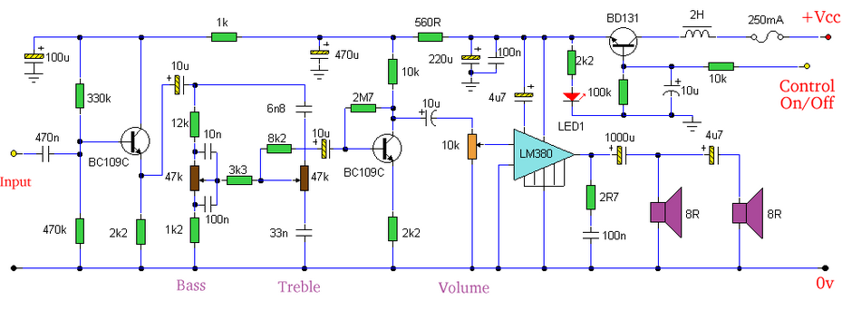
Built around an LM380, this amplifier includes tone controls and electronic soft switching. The soft switching circuitry ensures power is balanced. The LM380 is a power audio amplifier capable of delivering up to 14 watts of output power. It is...
Precision high voltage regulator power supply. Refer to the corresponding page for an explanation of the related circuit diagram for the power supply. This simple switching regulator circuit provides a 5 V output, with the input supplied by a...
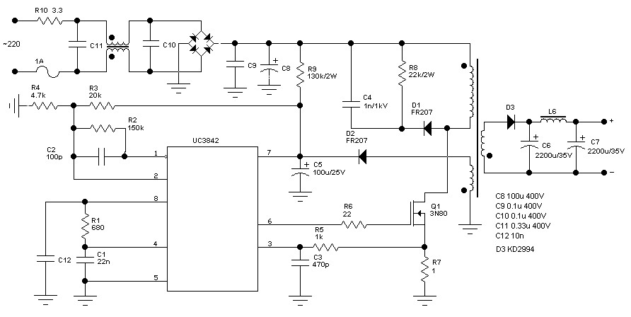
The schematic diagram originates from a 60 Watt Switching Power Supply. It details a power supply designed for a 70W stereo amplifier, utilizing the KA2S0880 chip, which encompasses all necessary components for constructing the primary section of the power...
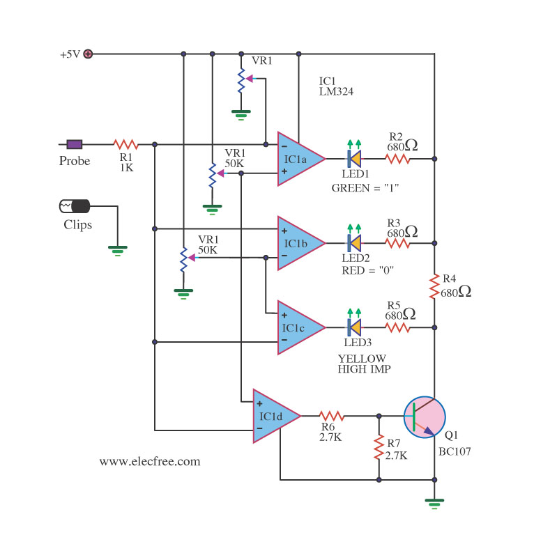
A logic probe is a useful tool for checking digital circuits. It functions similarly to a meter, which is employed to measure power in electrical circuits. A logic probe is an essential diagnostic instrument in digital electronics, designed to analyze...
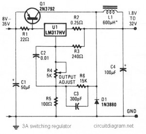
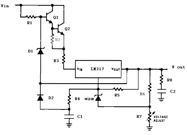
The circuit diagram presented is a simple and cost-effective switching voltage regulator capable of delivering an adjustable output voltage range from 1.8V to 32V with a maximum static current of 3A. This regulator utilizes the adjustable LM317HV IC along...