
High-precision high-impedance instrument OPA2111 amplifier circuit

The OPA2111 is a precision operational amplifier characterized by its low noise and high input impedance, making it suitable for applications requiring accurate signal amplification. The configuration described utilizes a differential amplifier setup, which is essential for rejecting common-mode signals while amplifying the desired differential signal.
In this circuit, the gain is determined by the resistors R1 and R2, with the formula for voltage gain being Av = 10 (1 + 2R2 / R1). This configuration allows for a significant amplification factor of 1000, which is beneficial in applications where signal levels are low and need to be boosted for further processing or analysis.
The differential amplifier stage enhances the common-mode voltage range, allowing the instrumentation amplifier to handle input signals that may vary significantly without distortion or loss of fidelity. By extending the common-mode input voltage range to 10V, the amplifier can effectively process signals from various sources, including sensors and transducers, which may operate within this voltage range.
Overall, the OPA2111 amplifier configuration presented is an effective solution for applications requiring high precision and high input impedance, ensuring accurate signal amplification while maintaining the integrity of the input signal.Shown for the high-precision, high-impedance instrument OPA2111 amplifier configuration. Total voltage circuit illustrated magnification Av = 10 (1 + 2R2 / R1) = 1000 times. A gain stage 10 of the differential amplifier circuit is to expand the instrumentation amplifiers input common-mode voltage range of 10V.
Related Circuits
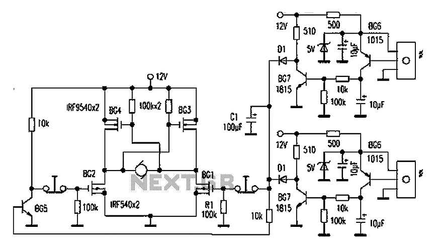
This is a simple and cost-effective inverter designed to power a small soldering iron (25W, 35W, etc.) when a mains supply is not available. The circuit utilizes eight transistors along with several resistors and capacitors. Transistors Q1 and Q2,...
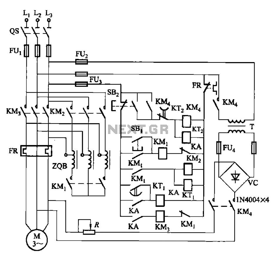
The circuit is illustrated in Figure 3-141. It includes a line autotransformer for voltage starting and dynamic braking. The circuit features a buck start button (SBi) and a stop button (SBz). The buck start-up time is controlled by the...
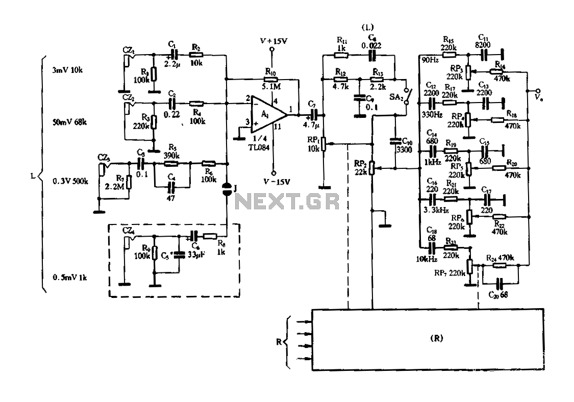
Figure 3-25 illustrates a hybrid circuit featuring four input preamplifiers. The components C1, C2, C3, and C4 can accept signals from a microphone, line, phono, and crystal head respectively. The configuration allows for the individual or simultaneous entry of...
Automatic door control systems typically have a high market price for finished products. The proposed method is suitable for home use, utilizing easily accessible components. This design is ideal for those interested in creating their own automatic door system....
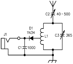
A crystal radio receiver is a very simple radio receiver that requires no battery or external power source, operating solely on the energy harvested from radio waves through a long antenna. A crystal radio receiver is a passive radio receiver...
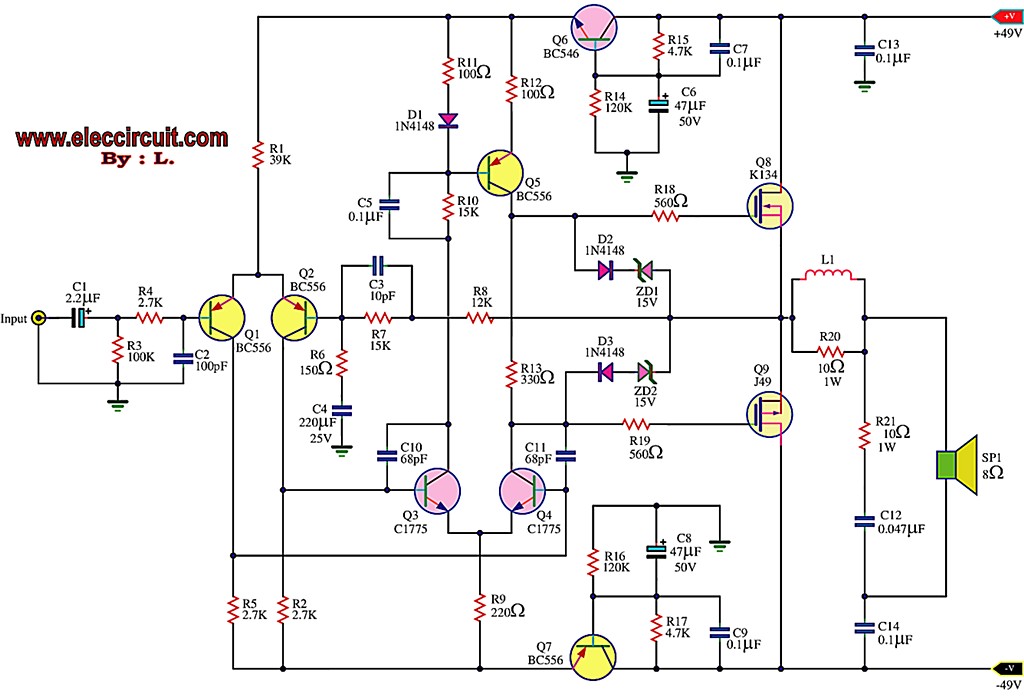
This is the first MOSFET power amplifier designed, featuring a comprehensive circuit. As a 60-watt power amplifier, it is adequate for typical usage. The 60-watt MOSFET power amplifier circuit is designed to deliver high efficiency and robust performance for audio...