
understanding fm transmitter circuit
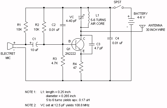
The electret microphone is a type of condenser microphone that utilizes an electret material to provide a permanent electric charge, allowing it to convert sound waves into electrical signals. The microphone's output current is influenced by sound pressure levels, resulting in a modulation of the voltage across the associated resistors in the circuit. Resistor R1 serves as a load for the microphone, and its voltage drop reflects the microphone's output signal.
The coupling capacitor C1 is crucial for isolating the AC signal from the DC biasing network while allowing the audio signal to pass through to the base of the transistor. The transistor is configured as an amplifier, where the base is biased to a stable voltage through resistors R2 and R3. This biasing ensures that the transistor operates in its active region, allowing for effective amplification of the audio signal.
Resistor R4 plays a significant role in setting the gain of the amplifier stage. The voltage drop across R4 changes in response to variations in the base voltage, which is affected by the input signal from the microphone. The amplified output can be further processed or used to drive subsequent stages in the audio signal chain.
In terms of modulation techniques, amplitude modulation (AM) involves varying the amplitude of the carrier signal based on the input audio signal. The question regarding frequency modulation (FM) suggests a consideration of how the circuit might behave if frequency modulation were to occur, which typically requires a different approach to signal processing.
Capacitor C3's function is crucial to the stability of the circuit. It may serve to stabilize the collector-emitter voltage of the transistor, ensuring consistent operation under varying input conditions. The role of capacitor C2 as a bypass capacitor requires further analysis; bypass capacitors are typically employed to filter out high-frequency noise and stabilize voltage levels, often connected to ground to provide a reference point for AC signals.
Overall, the described circuit demonstrates key principles of audio signal amplification and modulation, with components working in tandem to process sound signals effectively. Further investigation into the specific roles of capacitors and the modulation techniques employed would enhance the understanding of the circuit's operation.The electret microphone has a current of 200uA which changes by +- 3 uA depending on sound waves. This sets the voltage across R1 to 2V and the voltage across the mic to 4 volts. As the sound hits the mic the current through R1 increases slightly reducing the voltage across the mic. Is that what is happening This changing voltage is passed on by the coupling cap, C1 to the base of the transistor, which is biased by R2 & R3 to approx 2V. The voltage across R4 with no signal on the mic will be Vb - 0. 7 (drop across vbe), 1. 3 volts. As the voltage at b changes R4 will change by the same amount. This change in voltage is seen at the base of the tank circuit. And the signals voltage is increased/decreased. Isn`t this what happens in AM As wouldn`t the capacitance need to change in order to get Frequency modulation And if it was amplitude modulation occuring in the FM spectrum, then how would a radio receiver be able to demodulate the signal At this point I`m not sure what is happening at the capacitor C3, what is that doing Is it holding CE at a fixed voltage And is it along with capacitor C2 considered a bypass capacitor Or do bypass capacitors need to be connected to ground 🔗 External reference
Related Circuits
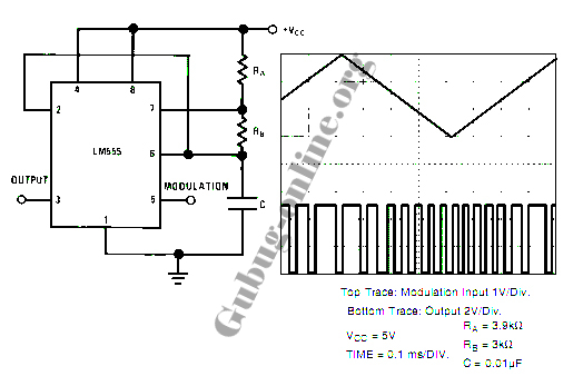
This design circuit for a pulse position modulator can be easily constructed using a 555 integrated circuit (IC). The pulse position modulator modulates the on-period while maintaining a fixed off-period. The circuit utilizes the 555 timer IC in astable mode...
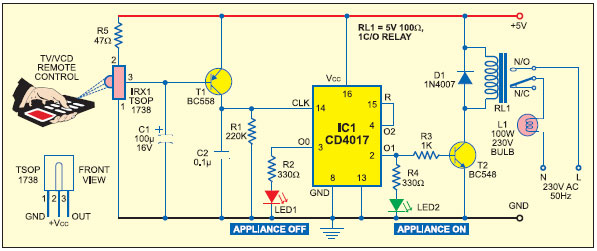
It is essential to consider migrating to PIC microcontrollers and exploring compilers such as those offered by Proton Smart, which include Sony IR and Philips RC5 codecs. This approach is particularly advisable for security-sensitive applications. Additionally, Bluetooth and Wi-Fi...
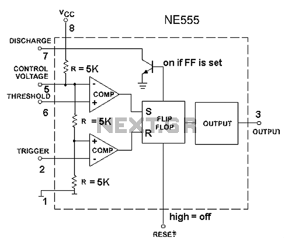
The 555 timer circuit, regardless of the manufacturer, has a consistent internal structure and performance. Various manufacturers produce different models of the 555 timer, including MC555, CA555, XR555, LM555, as well as domestic models like SL555, FX555, and 5G1555....
A Variable DC Power Supply is an essential tool for electronics hobbyists. This circuit is not entirely new, but it is simple, reliable, robust, and short-proof, offering variable voltage up to 24V and variable current limiting up to 2A....
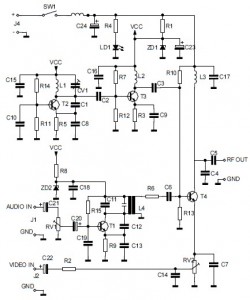
This is the circuit diagram of an audio/video modulator. The circuit converts audio and video signals into a UHF TV signal. It is designed to connect a video signal originating from a camera or other video source to a...
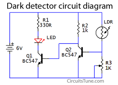
This is a basic dark detector or sensor circuit diagram based on a photoresistor (LDR) and a few components. The dark detector circuit utilizes a photoresistor (LDR) as the primary sensing element. The LDR is a light-dependent resistor that changes...
Warning: include(partials/cookie-banner.php): Failed to open stream: Permission denied in /var/www/html/nextgr/view-circuit.php on line 713
Warning: include(): Failed opening 'partials/cookie-banner.php' for inclusion (include_path='.:/usr/share/php') in /var/www/html/nextgr/view-circuit.php on line 713