
Dark detector circuit using LDR LED
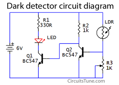
The dark detector circuit utilizes a photoresistor (LDR) as the primary sensing element. The LDR is a light-dependent resistor that changes its resistance based on the intensity of light falling on it. In low-light conditions, the resistance of the LDR increases significantly, allowing the circuit to detect darkness.
The circuit typically comprises a few key components: the LDR, a resistor, a transistor, and an LED or buzzer for output indication. The LDR is connected in a voltage divider configuration with a fixed resistor. As ambient light decreases, the voltage across the LDR increases, which can be fed into the base of a transistor.
When the voltage at the base of the transistor exceeds a certain threshold, the transistor turns on, allowing current to flow from the collector to the emitter. This current can then energize an output device such as an LED or a buzzer, providing a visual or audible indication of low light conditions.
To enhance the circuit's functionality, additional components such as a potentiometer may be included to adjust the sensitivity of the LDR, allowing for tuning based on the specific application or environment. Furthermore, a capacitor can be added in parallel with the output device to create a delay in response time, preventing rapid on-off cycles in fluctuating light conditions.
Overall, this dark detector circuit serves as a fundamental example of using an LDR in electronic applications, showcasing the principles of light sensing and transistor switching in a straightforward design.This is a basic dark detector/sensor circuit diagram based on a Photo Resistor (LDR) and few numbers of parts.. 🔗 External reference
Related Circuits

Using a Thomson TEA2025, this stereo amplifier delivers 1 W per channel into a 4-ohm load with a 9-V supply. The input sensitivity is 25 mV peak-to-peak for full output. It is important to ensure that pins 4, 5,...
In Fig. 1 A precision DC undervoltage relay switch. The op-amp is wired as a voltage comparator, with a reference voltage applied to pin 2 and the test voltage applied to pin 3: the relay turns on when the...
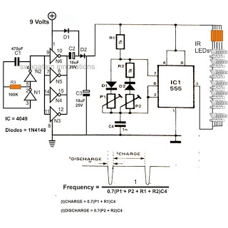
The 4049 section serves as a fundamental voltage doubler circuit, enhancing a 9 V supply to approximately 15 V. This elevated voltage subsequently acts as the supply voltage for the following 555 pulse modulator section. A key characteristic of...
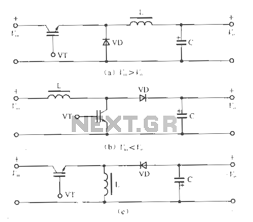
The circuit operates without isolation for both input and output voltage, utilizing a working switch along with an inductor (L), diode (D), and capacitor (C) to form a basic inverter circuit. There are three types of converters: the step-down...
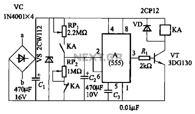
The circuit, as illustrated in Figure 3-82, employs a 555 IC to control a motor automatically, managing its start and stop cycles. The running and stopping times of the motor can be adjusted by modifying the values of potentiometers...
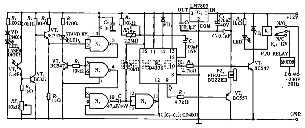
Circuit T operates on the principle of utilizing a laser diode LED as a light emitter. This circuit incorporates a laser diode that serves similar functions as a light-emitting diode. It features a resistor (R) and a diode (VD)...