
Unidirectional motion sensor
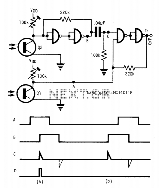
This circuit employs two phototransistors, Q1 and Q2, positioned at a defined distance apart to create a directional sensing mechanism. The operational principle relies on the interruption of light beams directed toward each phototransistor. When an object approaches the sensors, it will first obstruct the light reaching either Q1 or Q2, depending on the direction of movement.
For instance, if an object moves from left to right, it will first block the light from reaching Q1. This action triggers Q1 to switch from an off state to an on state, generating a voltage change that is detected by the circuit. As the object continues moving and subsequently blocks the light to Q2, a second voltage change occurs, which is processed to output a pulse at D. This pulse signifies the detection of an object moving in the intended direction.
Conversely, if the object moves from right to left, it will first block the light reaching Q2, causing it to activate before Q1. Since the circuit is designed to only recognize the pulse generated when Q1 is triggered before Q2, no output pulse is generated at D in this scenario.
The requirement that the object’s length must exceed the distance between Q1 and Q2 ensures that the sensors do not trigger simultaneously, which would lead to ambiguous readings. This length requirement guarantees that the object will always trigger Q1 before Q2 when moving in the correct direction, thereby ensuring reliable operation of the circuit.
The design can be utilized in various applications, such as automated counting systems, security alarms, or any scenario where directional movement detection is essential. By fine-tuning the sensitivity of the phototransistors and adjusting the distance between them, the circuit can be optimized for different object sizes and environmental conditions.This circuit detects an object passing in one direction but ignores it going the opposite way. Two sensors define the sense of direction. The object blocks the light to phototransistor Ql or Q2 first dependent on the direction of approach. When the object passes Ql then Q2, an output pulse is generated at D; while no pulse is seen at D as the object passes Q2 then Ql.
Object length (measured along the direction of the two sensors) should be greater than the separation of the two sensors Ql and Q2. 🔗 External reference
Related Circuits
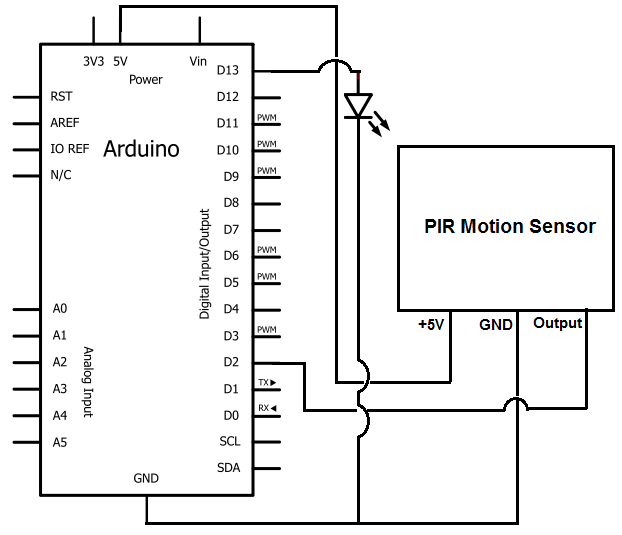
Once the motion sensor detects motion, the Arduino can be programmed to activate an LED, turn on a motor, sound a buzzer, etc. In this circuit, for simplicity, an LED will be turned on when the motion sensor detects...
The TMP03 is a complete temperature data-acquisition system on a monolithic silicon chip. Including a silicon-based sensor, internal voltage reference, and sigma-delta A/D converter, it fits in a 3-pin (power, common, and output) TO-92 transistor package. Its digital output...

The schematic for this project is designed to be very simple, utilizing a minimal number of components to keep costs and assembly time low. The primary components in the schematic include the PIC 18F452 microcontroller, a tilt sensor, and...
A simple tool to check the degree of radiation from an electric or electronic instrument. The LEDs in the circuit will provide a running light pattern when the circuit detects electromagnetic radiation from the device. It can identify radiation...
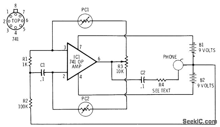
The 741 operational amplifier is configured as an audio oscillator using Radio Shack 276-677 photocells in the feedback circuits. When light strikes photocell PC1, its resistance decreases, resulting in a corresponding decrease in the frequency of the audio tone...
The ultrasonic sensor circuit comprises a transmitter and a receiver, which are essential for remote control applications. The circuit operates at sound frequencies above 20 kHz, typically between 40 kHz and 50 kHz, powered by a 9V battery. When...