
AUDIBLE LIGHT SENSOR
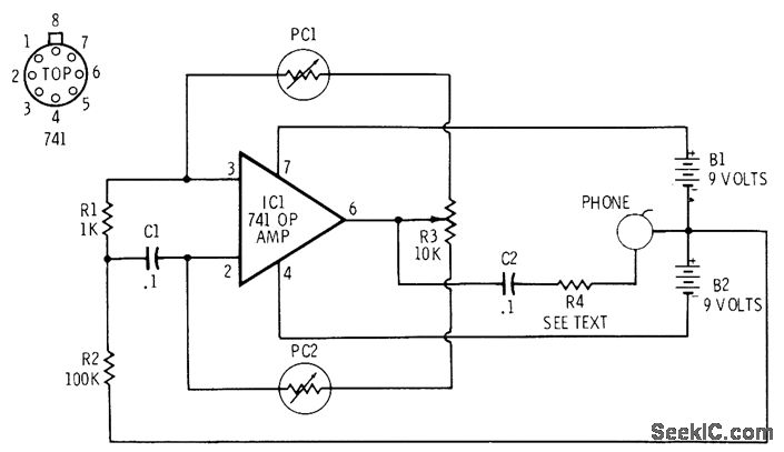
The circuit utilizes a 741 operational amplifier (op-amp) configured to function as an audio oscillator, generating sound frequencies that can be modulated by varying light levels. The key components include two photocells (PC1 and PC2) that serve as light-dependent resistors, which change their resistance based on the amount of light they are exposed to.
In this setup, PC1 is connected in such a way that as light intensity increases, its resistance decreases, leading to a reduction in the output frequency of the oscillator. This behavior can be utilized in applications where a decrease in frequency corresponds to lower light levels, creating an inverse relationship between light and audio output.
On the other hand, PC2 is connected to the non-inverting input of the op-amp. When the light intensity increases on this photocell, it results in a decrease in resistance, which in turn increases the frequency of the audio tone produced. This setup allows for a dual modulation effect, where one photocell decreases frequency while the other increases it, creating a dynamic audio response to varying light conditions.
Resistor R4 is included in the circuit to control the volume output of the audio signal, allowing for adjustments based on user preference or environmental conditions. Meanwhile, R3 acts as a balancing control for the photocells, ensuring that their responses to light are appropriately matched for the desired audio effect.
This circuit exemplifies the use of light-sensitive components in audio applications, providing a unique interface for sound modulation based on environmental light levels. The design is documented in "Integrated Circuit Projects, Vol. 2" by F. M. Mims, which serves as a reference for further exploration of similar electronic projects.741 opamp is connected as audio oscillator with Radio Shack 276-677 photocells in feedback circuits. When light strikes PC1, its resistance decreases and frequency of audio tone in headphone decreases correspondingly. When light strikes PC2, which is connected to noninverting input of 741, increase in illumination serves to increase frequency.
Cho ose R4 to reduce volume to desired level. R3 is balancing control for photocells. -F. M. Mims, "Integrated Circuit Projects, Vol. 2, " Radio Shack, Fort Worth, TX, 1977, 2nd Ed. , p 81-86. 🔗 External reference
Related Circuits
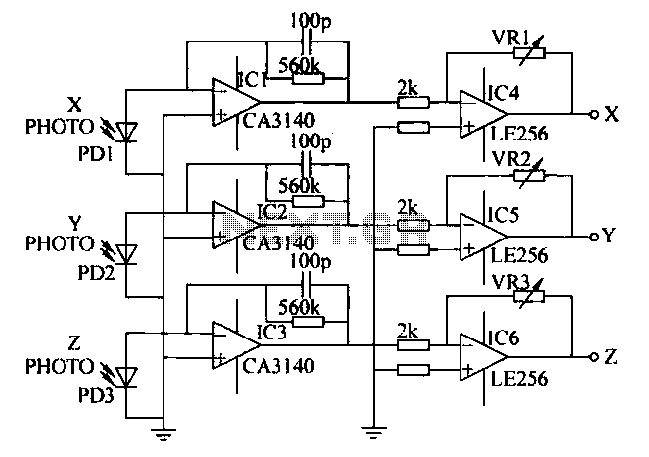
A semiconductor color sensor is designed to identify the color of an object using three photodiodes (PD1, PD2, PD3) and three corresponding color filters (X-PHOTO, Y-PHOTO, Z-PHOTO). Each photodiode is paired with a specific color filter: red (R), green...
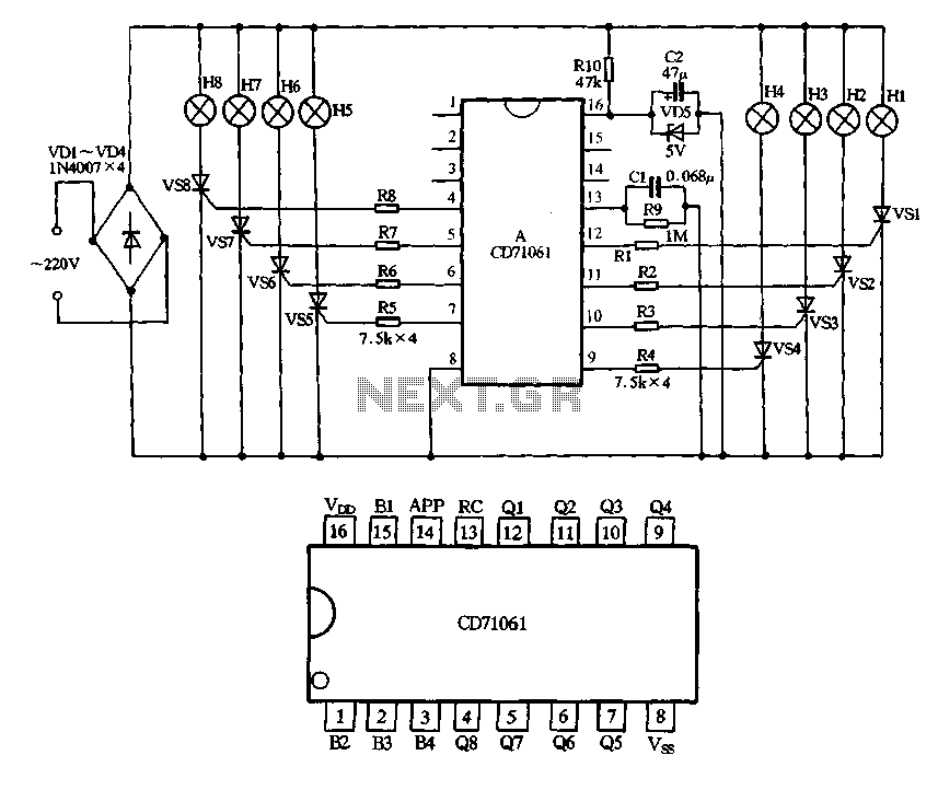
A 220V AC input is processed through a VD4 bridge rectifier, followed by a resistor R10 buck regulator, a VD5 regulator, and a capacitor C2. This setup filters the supply to power the manifold. The output trigger signal from...
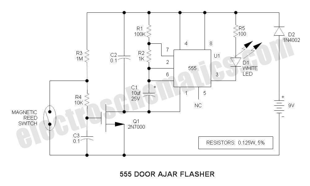
A magnet is positioned on the door, while a magnetic reed switch is installed on the door casing. When the door is closed, the circuit is disabled. When the door is opened, the circuit becomes active. In this circuit design,...
Parts List The circuit was specifically designed for shop window animation as it utilizes a capacitive sensor that is activated by a touch control system. The circuit is intended for enhancing visual displays in retail environments by creating dynamic animations...
This project demonstrates the construction of a simple LED light string display utilizing seven 24V LED light strings. The project was designed for Christmas 2009 to adorn a balcony with lights. The light strings are widely available, particularly in...
Many of today's high-performance FPGAs, microprocessors, DSPs, and industrial/embedded subsystems require sequencing of the input power PS10 and PS11. Historically, this has been achieved through: i) discrete methods using comparators, references, and RC circuits; ii) expensive programmable controllers; or...
Warning: include(partials/cookie-banner.php): Failed to open stream: Permission denied in /var/www/html/nextgr/view-circuit.php on line 713
Warning: include(): Failed opening 'partials/cookie-banner.php' for inclusion (include_path='.:/usr/share/php') in /var/www/html/nextgr/view-circuit.php on line 713