
Basic Tilt Sensor Tutorial Circuit

The circuit schematic is structured to facilitate a straightforward implementation of the described components. The PIC 18F452 microcontroller serves as the central control unit, managing inputs from the tilt sensor and controlling the LED output. The tilt sensor is a crucial component that detects orientation; its output is directly interfaced with the microcontroller's PORTA RA0 pin. This configuration allows the microcontroller to read the sensor's state, determining whether the device is tilted or upright.
The power regulation circuit ensures that the microcontroller and other components receive a stable +5V supply. The 7805 voltage regulator is essential for converting the battery voltage to the required level, while the capacitor stabilizes the output voltage, minimizing fluctuations that could affect circuit performance. The resistor and LED indicator provide a visual cue for power status, enhancing usability by confirming that the circuit is operational.
The LED bar, which features 10 individual LEDs, serves as an output display for the project. Although only 8 LEDs are connected to the microcontroller's PORTD, this configuration is sufficient to convey the necessary information to the user. Each LED can represent different states or levels of the tilt sensor's readings, providing a clear visual representation of the device's orientation.
Overall, the simplicity of the circuit design, combined with the effective use of the PIC 18F452, tilt sensor, and LED bar, makes this project an excellent example of efficient electronic design. The decision to limit the number of connected LEDs is a practical choice, balancing functionality with component availability and cost-effectiveness. This schematic effectively demonstrates the principles of microcontroller-based design and sensor integration in a user-friendly format.The schematic for this project has been kept super simple with very few parts keeping the total cost very low and assembly time low. The main parts in the schematic are the PIC 18F452, Tilt Sensor and LED Bar. The power regulation circuit is in the lower right corner. It consists of the battery, a 7805, a capacitor and a resistor+led power led circuit, which lets you know power is on. The tilt sensor circuit is connected to the PIC`s input at PORTA`s RA0. It is pulled high to +5v when tilted and when not tilted, it acts like a button that has been pushed, connecting RA0 to ground. The LED output bar actually has 10 LEDs, however only 8 are connected since PORTD only has 8 output pins.
You could use other ports to get all 10 LEDs lit up, but I felt 8 LEDs was enough to get the point across for this project. 🔗 External reference
Related Circuits
Circuit Magic is an electrical circuits simulation program specifically designed for students teaching basics electronics, electrical laws & circuit theory. Unlike many electronic circuit analyzers, Circuit Magic can analyze circuits like a man. Circuits are simulated step by step,...

Circuit for Grundig 5441 TV. If there are any issues related to this circuit, please provide additional information about the problem for further assistance. By accessing the Fixya site, users acknowledge that they have read and agreed to its...
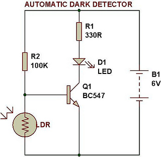
An automatic dark detector senses darkness. As the light level decreases and the light-dependent resistor (LDR) reaches the maximum threshold resistance, the circuit automatically activates the LED D1. Conversely, a light detector senses light, and when the light level...
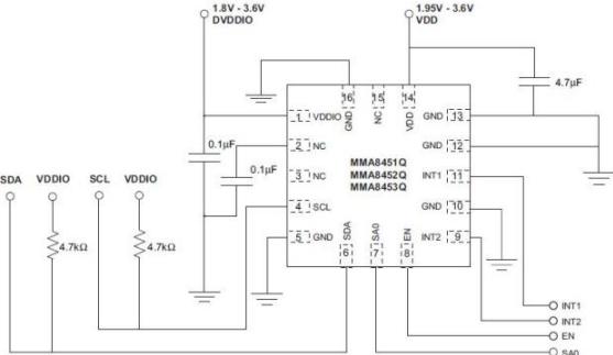
The task involved implementing and programming all hardware devices to make data accessible to the receiver program running on a PC. This included configuring all Prospeckz devices and establishing protocols for radio transmission communication back to the PC. Additionally,...

AC solenoid DC circuit operation operates similarly to a DC contactor circuit, but the AC solenoid pull circuit is illustrated in the provided figure. The capacitance C is generally between 1-10 microfarads (µF), with a minimum of 20 microfarads...
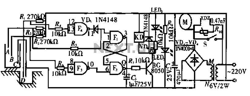
The circuit operates by monitoring the water level in a tank. When the water level falls below a specified point (F), the RS flip-flop (F2) is activated, producing a high Q output that energizes a relay to start the...
Warning: include(partials/cookie-banner.php): Failed to open stream: Permission denied in /var/www/html/nextgr/view-circuit.php on line 713
Warning: include(): Failed opening 'partials/cookie-banner.php' for inclusion (include_path='.:/usr/share/php') in /var/www/html/nextgr/view-circuit.php on line 713