
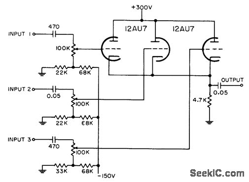
UNITY GAIN FOUR INPUT AUDIO MIXER
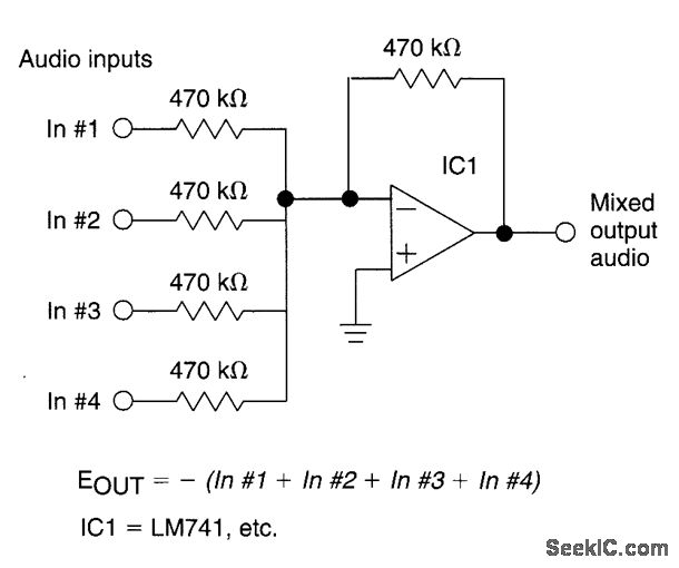
The described circuit operates as a voltage buffer or unity-gain amplifier, utilizing operational amplifiers (op-amps) to ensure that the output voltage closely follows the input voltage. Each of the four inputs is connected to the non-inverting terminal of an op-amp, while the output of the op-amp is fed back to the inverting terminal through a feedback resistor of 470kΩ. The input resistor, also rated at 470kΩ, serves to limit the input current and stabilize the circuit.
In a typical application, the circuit can be used in signal conditioning, where multiple signals need to be processed without introducing any gain or attenuation. The unity gain ensures that the output signal is an accurate representation of the input signal, making it ideal for interfacing with other stages of a system, such as analog-to-digital converters or further amplification stages.
The choice of resistor values (470kΩ) plays a crucial role in determining the input impedance of the circuit. With both the input and feedback resistors being equal, the input impedance is effectively high, allowing the circuit to interface with various signal sources without loading them down. This characteristic is particularly beneficial in applications where the source impedance may be high.
Furthermore, the circuit's design can be expanded to include additional features, such as filtering or buffering, by incorporating capacitors or additional op-amp stages, depending on the specific requirements of the application. Overall, this configuration provides a robust solution for maintaining signal integrity across multiple inputs, ensuring that the output remains faithful to the original input signals.The circuit has four inputs. The voltage gain between each input and the output is held at unity by the relative values of the 470k © input resistor and the 470k © feedback resistor. 🔗 External reference
Related Circuits
This application note describes the evaluation board for the AD7892-2, a 12-bit analog-to-digital (A/D) converter. The AD7892-2 is a high-speed, low-power device capable of 500 ksps sampling rate, operating from a single +5V supply. It features an on-chip track/hold...
The TDA2549 is a complete intermediate frequency (IF) circuit that includes automatic frequency control (AFC), automatic gain control (AGC), demodulation, and video preamplification capabilities for multistandard television receivers. It can process both positively and negatively modulated video signals in...
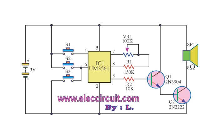
The circuit operates using a UM3516 integrated circuit (IC1), which is designed to generate sound. The output sound is produced at pins 7 and 8 of IC1, and the components R1 and VR1 are utilized to control the frequency...
Each grid is biased to cutoff, allowing the mixer to accept only positive-polarity pulses with sufficient amplitude to overcome this bias. -NBS, "Handbook Preferred Circuits Navy Aeronautical Electronic Equipment," Vol. 1, Electron Tube Circuits, 1963, p N4-2. In a typical...
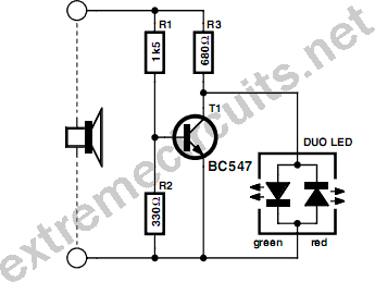
This circuit indicates the power level delivered to a loudspeaker. A dual-color LED displays green at approximately 1 watt, orange at 1.5 watts, and bright red at levels exceeding 3 watts. The circuit is connected in parallel with the...
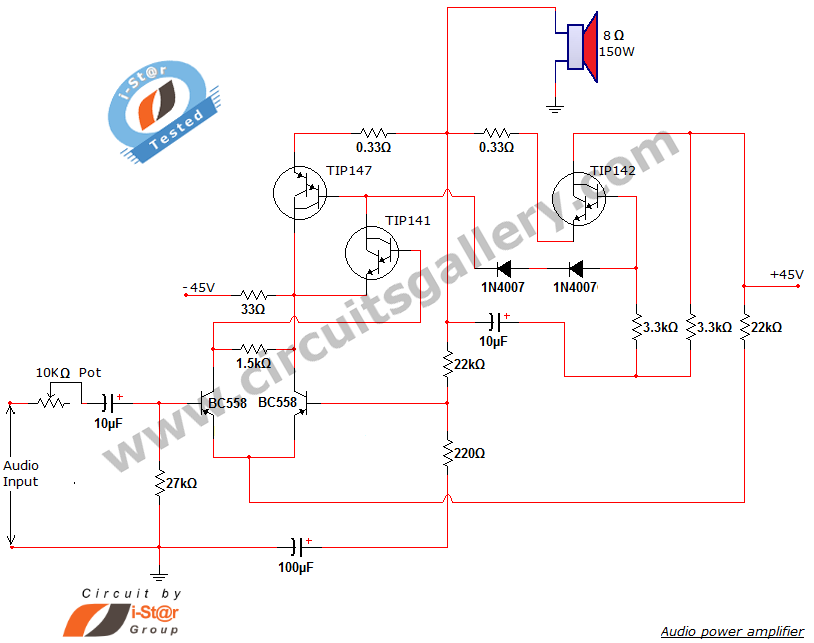
This document presents a new audio power amplifier schematic utilizing TIP darlington pair transistors. It is suitable for both home audio and car audio amplifiers. The TIP142 and TIP147 darlington pair transistors create a push-pull high-power amplifier configuration, while...