
Simple home audio power amplifier circuit schematic
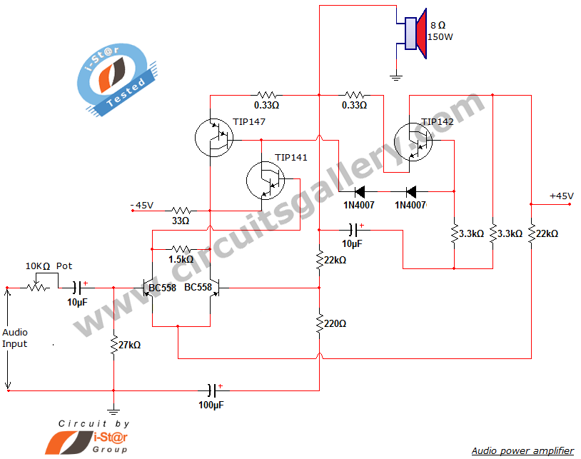
This audio power amplifier circuit is designed for high efficiency and low distortion, making it suitable for a variety of audio applications. The TIP142 and TIP147 transistors are selected for their high current gain and ability to handle significant power levels, which are essential for driving larger speakers effectively. The push-pull configuration allows for better performance in terms of linearity and reduced crossover distortion, which is particularly important in audio amplification.
The preamplifier stage, formed by the BC558 transistors, plays a crucial role in amplifying the weak audio signal before it reaches the power amplifier stage. This differential amplifier configuration enhances the signal-to-noise ratio, ensuring that the audio output remains clear and free from unwanted noise. The 10 µF DC decoupling capacitor is vital in blocking any DC offset present in the audio signal, which could otherwise affect the performance of the amplifier.
The power supply requirements of +/-40V at 5A ensure that the amplifier can deliver its full rated power without distortion. The specified 30V-0-30V transformer is suitable for providing the necessary voltage levels for the dual power supply, allowing the amplifier to operate efficiently under various load conditions.
Overall, this audio power amplifier schematic represents a cost-effective and efficient solution for audio amplification needs, making it an excellent choice for hobbyists and professionals alike. The detailed component specifications and circuit design ensure that users can replicate the circuit with ease, achieving high-quality audio performance in their applications.Here is a new audio power amplifier schematic built around TIP darlington pair transistors. You can use this circuit for home audio power amplifiers and car audio amplifiers. The TIP142 and TIP147 darlington pair transistors forms a push pull high power amplifier configuration while the two BC558 PNP transistor provides a mini audio pre amplifier circuit. The audio signal is applied to the pre amp through a capacitor, then it is coupled to the push pull power amp via TIP141 transistor. The values and ratings of different components of power amplifier design are also given in this article.
Implementation cost of this mini audio amplifier circuit is too cheap, near $5. The circuit can deliver 150 W RMS to a 8 © (150 Watt power amplifier). Our new audio power amplifier project is based on TIP 142 and TIP 147 (complementary darlington pair power transistors which can handle 5 A current and 100V). The two PNP (BC 558) transistors forms a pre amplifier section to the preceding high power push pull amplifier built around TIP141, TIP 142 and TIP 147 darlington pair transistors.
We are using 2 PNP transistors to form a preamplifier section, it is nothing but a differential amplifier to improve overall performance of the amplifier. The application of a differential amplifier in the input phase reduces noise. Input signal is applied to the differential amplifier section via 10 µF DC decoupling capacitor. Capacitor removes the DC voltage from the input audio signal. A complementary class AB push pull power amplifier stage is built around the TIP darlington pair transistors to drive the 8 © 150 watt speaker (The circuit can deliver 150 W RMS to a 8 ©).
+/-40V, 5A dual power supply is necessary to provide supply for this simplest amplifier circuit. Use 30V-0-30V step down transformer and construct a dual lab power supply for this project. 🔗 External reference
Related Circuits
In the circuit's resting (dark) state, current flows through the electromagnet M. When light shines on the phototransistor, it turns on, causing the final stage transistor to enter the OFF state, which releases the solenoid. A 1M ohm feedback...

The 60 Watt linear amplifier is a straightforward all-solid-state circuit utilizing the power MOSFET IRF840. The IRF series of power transistors are available in various voltage and power ratings. A single IRF840 can handle a maximum power output of...
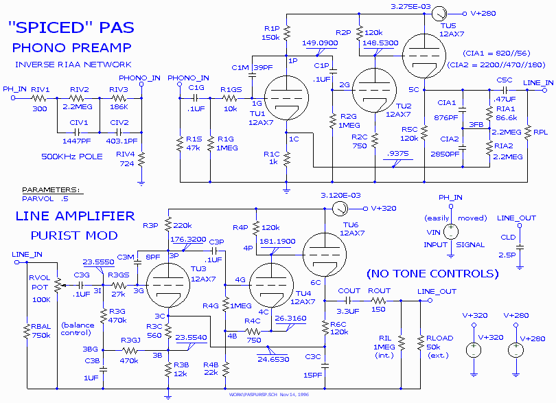
One of the main considerations in phono preamplifier design is the choice between active (feedback) and passive equalization. An ideal feedforward preamplifier for a moving magnet cartridge would provide approximately 40 dB of gain before the equalizer (more for...
This blog provides insights into SMPS (Switched-Mode Power Supply) circuit diagrams. It offers valuable information for those interested in understanding this topic. Switched-Mode Power Supplies (SMPS) are crucial in modern electronic devices due to their efficiency and compact design. An...
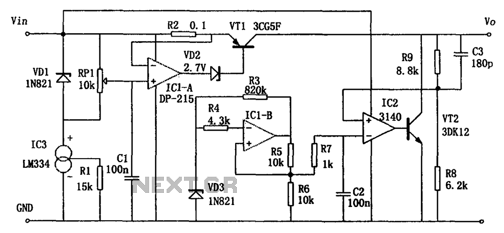
The circuit functions as a switching power supply designed to operate alongside a linear regulated power supply. Key characteristics include high efficiency and low dropout voltage. It effectively filters out high-frequency ripple voltage and manages instantaneous voltage variations, making...
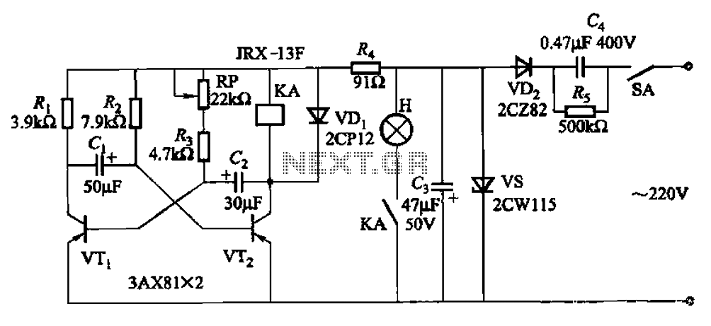
The circuit features a self-excited multivibrator composed of transistors VTi and VTZ. It includes an adjustment potentiometer RP and two RC networks that influence the transistors' parameters, specifically the timing for light activation and deactivation. The described multivibrator circuit utilizes...
Warning: include(partials/cookie-banner.php): Failed to open stream: Permission denied in /var/www/html/nextgr/view-circuit.php on line 713
Warning: include(): Failed opening 'partials/cookie-banner.php' for inclusion (include_path='.:/usr/share/php') in /var/www/html/nextgr/view-circuit.php on line 713