
UNIVERSAL BATTERY CHARGER

The charger circuit operates by detecting the battery voltage and adjusting the charging method accordingly. Initially, when the battery voltage falls below a certain threshold, the circuit employs a constant current charging technique, which is efficient for quickly replenishing the battery's charge. As the battery approaches its fully charged state, the circuit switches to a pulsed charging mode. This mode significantly reduces the risk of overcharging and prolongs battery life by preventing excessive heat buildup and electrolyte loss, common issues in traditional charging methods.
The LED indicator provides real-time feedback on the charging status. When the battery is charging, the LED illuminates, and as the battery reaches full charge, the LED dims, indicating that the battery can be left connected without the risk of overcharging. The adjustable variable resistor allows for precise calibration of the charging voltage, accommodating different battery configurations and types.
The charging current can be fine-tuned to suit the specific characteristics of the batteries being charged. For instance, the use of a 12-ohm resistor in conjunction with the LED's forward voltage ensures that the charging current remains within safe limits while optimizing charging efficiency. This adaptability makes the circuit suitable for various battery capacities, ranging from 500mAh to 1200mAh, across multiple voltage ratings of 4.8V, 6V, and 7.2V.
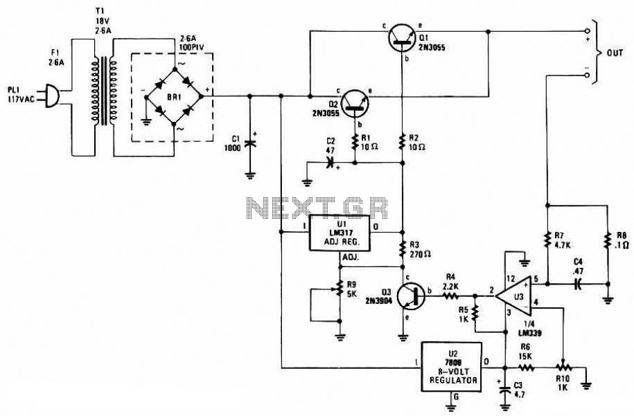
The power supply for the charger is a standard 12V DC source, which is commonly available and provides the necessary voltage for efficient operation. This design not only enhances the functionality of the charger but also ensures compatibility with a wide range of NiCd and NiMh batteries, making it a versatile tool for users with different battery needs.This is a charger circuit for both NiCd and NiMh Batteries. Some time ago I aquired an old commercial handheld-TRX which was powered by a 12 Volt NiCd-Battery pack (10 Button Cells each having a capacity of 280mAh). In fact this (at least 10 year) old battery is best because there is a very special charger used: When the Battery voltage is low it
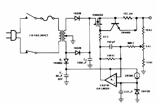
is charged with the usual constant current source in the normal way. But when the battery voltage increases, the charging current will become pulsed. A completly fully charged battery only requires short flashes to maintain its charge and terminal voltage. Here is the circuit diagram: The original circuit used some old-fashioned components, so I devised a completly new design using only standard, commonly available components.
The LED (green) shows that the battery is charged. A full battery is indicated when the LED is "dark" most of the time. Set the Charger to 1. 42 Volts for each cell (i. e. 5. 68V for a 4. 8V Battery-Pack) by adjusting the 47k variable resistor. The charging current is around 120mA and can be changed by adjusting the 12 Ohm resistor, or the forward votlage (colour) of the LED. At the moment I am using the new circuit for 4. 8V, 6V and 7. 2V Batteries having a capacity ranging from 500mAh to 1200mAh. 12vDC is used to power this charger. Here is a photograph of the completed project: 🔗 External reference
Related Circuits
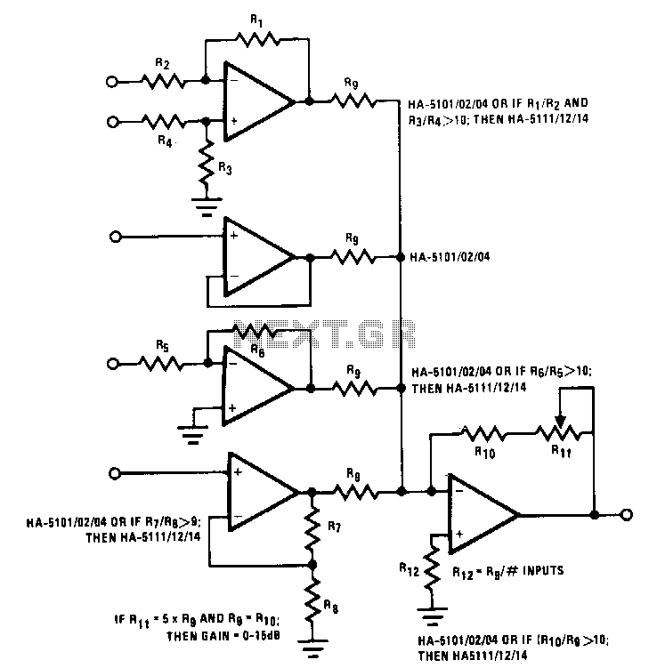
This circuit illustrates various possible buffer combinations. These include a differential input stage, a voltage follower, as well as both non-inverting and inverting stages. The allowable resistor ratios and recommended device types are also included. One restriction applies to...
This circuit functions as a night lamp when a wall mains socket is unavailable for plugging in a continuously operating small neon lamp device. To minimize battery consumption, it utilizes a single 1.5V cell, and a simple voltage doubler...
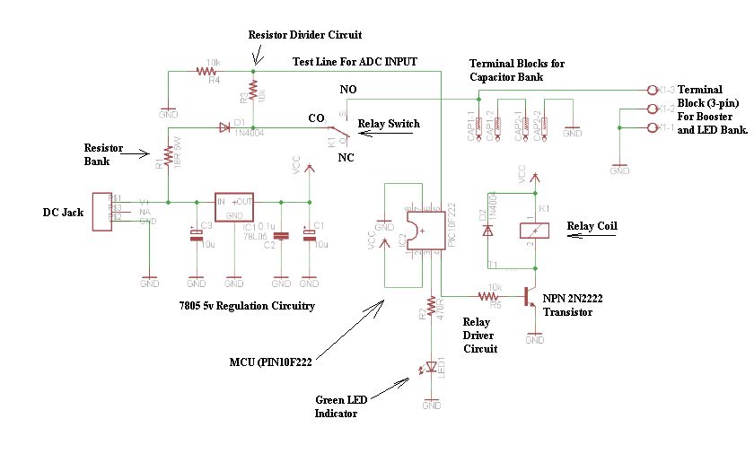
The schematic consists of four hardware blocks: 1) The wall transformer 2) The charging circuit 3) The control unit 4) The output stage. The circuit schematic is structured around four essential hardware blocks that facilitate the overall functionality of the...
This circuit outputs a voltage of 14 volts with a maximum current of 4A. It can be used for NiCad batteries and accumulators, both wet and dry types. However, the accumulator must be rated for 12 volts and have...
This battery charger circuit is regulated and adjustable, enabling it to charge most NiCAD batteries. It is suitable for single cells or multiple battery cells connected in series or parallel configurations. The maximum... This battery charger circuit is designed to...
This simple circuit provides a regulated output of 4.7 volts for charging a mobile phone. A USB outlet supplies 5 volts DC at 100mA, which is adequate for slow charging of mobile phones. Most mobile phone batteries are rated...