
Universal Four-Digit Keypad-Operated Switch - Construction Details

The electronic circuit described operates as a secure relay control system utilizing a keypad for user input. The relay is activated by pressing key "E", which allows current to flow through various components, including resistors and transistors, to energize the relay and illuminate an LED indicator. The complementary latch formed by transistors Q5 and Q6 ensures that the relay remains energized even after the key "E" is released, enhancing user convenience and system reliability.
The CMOS 4081 integrated circuit is central to the logic of the system, utilizing four two-input AND gates to manage the sequence of key presses required to deactivate the relay. Each gate is designed to latch its output high when the corresponding key is pressed in the correct sequence, maintaining the state of the system until all required keys (A, B, C, and D) are pressed. The design incorporates safety features, such as the ability to reset the sequence if an incorrect key is pressed, thereby preventing unauthorized access or unintended operation.
The use of a diode (D1) ensures that the key "E" can reset the system without allowing any unintended activation of the relay from the incorrect keys, maintaining clear operational boundaries. This design is particularly useful in applications where secure control over relay activation is necessary, such as in access control systems, alarm systems, or automated processes requiring user authentication. The careful arrangement of components and their interactions within the circuit exemplifies a well-thought-out approach to electronic design, ensuring both functionality and security.The key you`ve connected to "E" is used to energize the relay. And the four keys you`ve connected to A, B, C & D - are used to de-energize it. All the other keys on the keypad are connected to "F". = When "E" is pressed - current from the "Com" terminal flows through D2 and R9 - into the base of Q6. This switches Q6 on - and the transistor connect s the negative side of the relay coil to ground. This causes the relay energize. Q6 also connects the green LED to ground. This provides a visual indication that the relay is energized. = Q5 & Q6 are wired to form a complementary latch. When Q6 switches on - it also connects the base of Q5 to ground. In so doing - it switches Q5 on - and current through R10 & Q5 flows into the base of Q6. Thus, Q6 uses Q5 to supply itself with base current. In this way - the relay remains energized after "E" is released. For a detailed account of how a complementary latch works - click on the link below. = To de-energize the relay - you have to press A, B, C & D in the right order. The IC is a Cmos 4081. It has four two-input AND gates. These gates only produce a high output when both inputs are high. = To begin with - pin 1 is held high by R5. This enables gate 1. When "A" is pressed and pin 2 is taken high - the output of gate 1 - at pin 3 - goes high. This output does two jobs. Firstly, it latches itself on by holding pin 2 high through R2. In this way - pin 2 will stay high after "A" is released. Secondly, Pin 3 enables gate 2 by taking pin 5 high. In other words - pin 3 is doing for gate 2 - what R5 does for gate 1. = Now - in exactly the same way - when "B" is pressed and pin 6 is taken high, the output from gate 2 latches itself on through R3. And it enables gate 3 by taking pin 12 high. = Again - in exactly the same way - when "C" is pressed and pin 13 is taken high, the output from gate 3 latches itself on through R4.
And it enables gate 4 by taking pin 8 high. = Now - when "D" is pressed and pin 9 is taken high - the output from gate 4 latches itself on through R6. But this time it also switches Q4 on - through R8. = Q4 shorts the Q6 base current to ground. Without its base current - Q6 switches off. So the relay drops out - and the green LED is extinguished. = When Q6 switches off - the relay coil takes its collector high. It also takes the base of Q5 high. So Q5 switches off. And the base current Q5 was supplying to Q6 - is cut off. In other words - the complementary latch is unlatched. = The "right" keys are connected to A, B, C & D. The keys connected to "F" are the "wrong" keys. If one of the "wrong" keys is pressed - current through R7 will flow into the base of Q3. This switches the transistor on - and it connects pin 1 to ground. The initial gate 1 "enable" provided by R5 is removed - and pin 3 goes low. Pin 3 takes pin 5 low - so the gate 2 "enable" is removed. Pin 4 takes pin 12 low - so the gate 3 "enable" is removed. Pin 11 takes pin 8 low - so the gate 4 "enable" is removed. The sequence of support that each gate provides - by enabling its successor - is removed the moment pin 1 is taken low.
In other words - every time you press one of the "F" keys - the code entry sequence fails. = D1 allows the key you`ve connected to "E" - to act as though it`s connected to "F". But it prevents the keys you`ve connected to "F" - from behaving as though they are connected to "E". In other words - "E" is able to switch Q3 on - but "F" cannot energize the relay. = This is important for two reasons. Firstly, after the correct code has been entered - pin 10 is high and Q4 is switched on. Because Q4 diverts the Q6 base current to ground - "E" is prevented from turning Q6 on. However - D1 allows "E" to behave as though it`s connected to "F". "E" can switch Q3 on - take pin 1 low - reset the code entry sequence - and so switch Q4 off. When "E" is pressed - it begins by resetting the code entry sequence - and then it energizes the relay.
🔗 External reference
Related Circuits
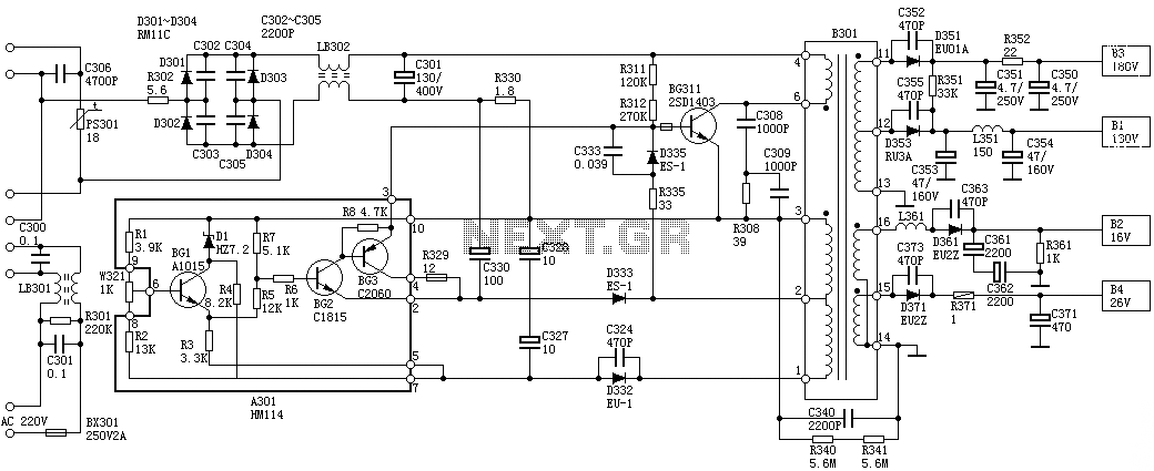
Oscillation: The positive terminal voltage of C310 is approximately 300V. The resistors R311 and R312 are connected to the switch BG311 at the B pole, while the B301 winding via the switching transformer (4) and (6) is connected to...

In conventional applications, switching-regulator integrated circuits (ICs) regulate the output voltage (VQVT) by controlling the current through an external inductor. However, the IC in configuration A utilizes a diode-capacitor network in place of the inductor, providing comparable performance for...
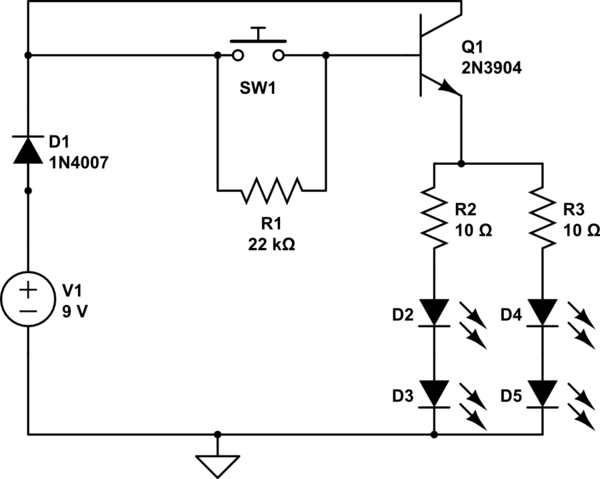
A circuit has been constructed that functions unexpectedly. The circuit utilizes red 5mm LEDs as diodes, a 3904 NPN transistor, and resistors as indicated in the schematic. Logically, pressing the push button normally open (PBNO) should result in the...
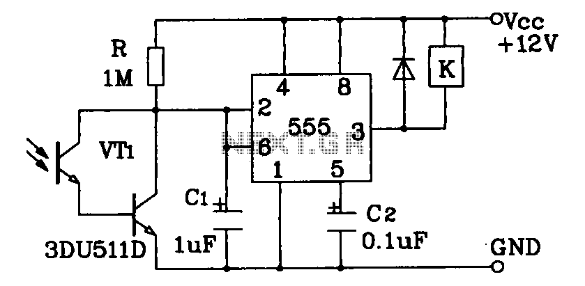
Darlington phototransistor type light-sensitive switch control circuit application. The Darlington type phototransistor serves as a sensitive element, capable of detecting low light levels for the detection of reflected light signals. The Darlington phototransistor circuit utilizes a pair of transistors configured...
Install the PIR module hanging from a 3-meter high mast to cover a 10-meter radius area. Connect its supply and relay terminals to the finished and enclosed circuit, ensuring the correct polarity is observed. A 4-core screened cable can...
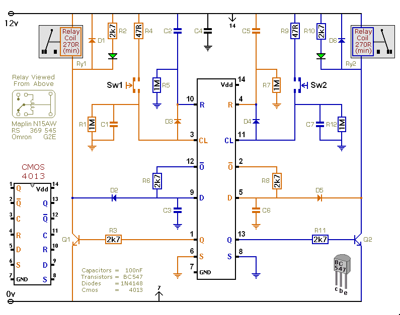
This versatile circuit offers a selection of different switching modes. It can function as two entirely separate toggle switches, with each push button successively energizing and de-energizing its corresponding relay. Alternatively, the two switches can be interconnected with diodes...