
UPS For Cordless Telephones
The described UPS circuit for cordless telephones presents a practical solution for maintaining functionality during power outages. The astable multivibrator configuration using the CD4047 IC ensures stable operation at 50 Hz, which is essential for driving the MOSFETs effectively. The choice of IRF540 MOSFETs provides sufficient switching capability to manage the required power levels with minimal heat generation. The push-pull topology enhances efficiency by allowing both halves of the transformer to be utilized, improving overall performance.
The filtering stage, incorporating a Metal Oxide Varistor (MOV), plays a critical role in protecting the circuit from voltage spikes that could occur during switching operations or due to external disturbances. The use of a standard 9V-0-9V transformer simplifies sourcing components and reduces costs, while the inclusion of dual LED indicators enhances user feedback regarding the operational status of the UPS.
Battery management is also a key consideration, with the option to use two 6V batteries providing flexibility in terms of sourcing and configuration. This modular approach allows for easy replacement and maintenance, which is beneficial in practical applications.
The overall design facilitates straightforward assembly on a general-purpose PCB, and the metal enclosure not only provides protection for the components but also aids in heat dissipation. By allowing for the potential upgrade to a 100W output, this UPS circuit can be adapted for varied applications beyond just supporting cordless telephones, making it a versatile solution for users requiring uninterrupted power supply for low-power electronic devices.Cordless telephones are very popular nowadays. But they have a major drawback, i. e. they cannot be operated during power failure. Therefore usually another ordinary telephone is connected in parallel to the cordless telephone. This results in lack of secrecy. UPS is a permanent solution to this problem. Since the UPS is meant only for the cordless telephone, its output power is limited to around 1. 5W. This is sufficient to operate most cordless telephones. as these employ only small capacity adapters (usually 9V/12V, 500mA), to enable the operation of the circuit and to charge the battery present in the handset. The UPS presently designed is of online type. Here the inverter is on` throughout, irrespective of the presence of the AC mains. When the AC mains is present, the same is converted into DC and fed to the inverter. A part of the mains rectified output is used to charge the battery. When the mains power fails, the DC supply to the inverter is from the battery and from this is obtained AC at the inverter output.
This is shown in fig. 1. The circuit wired around IC CD4047 is an astable multivibrator operating at a frequency of 50 Hz. The Q and Q outputs of this multivibrator directly drive power MOSFETS IRF540. The configuration used is push-pull type. The inverter output is filtered and the spikes are reduced using MOV (metal oxide varistor). The inverter transformer used is an ordinary 9V-0-9V, 1. 5A mains transformer readily available in the market. Two LEDS (D6 and D7) indicate the presence of mains/battery. The mains supply (when present) is stepped down, rectified and filtered using diodes D1 through D4 and capacitor C1. A part of this supply is also used to charge the battery. In place of a single 12V, 4Ah battery, one may use two 6V, 4Ah batteries (SUNCA or any other suitable brand).
The circuit can be easily assembled on a general-purpose PCB and placed inside a metal box. The two transformers may be mounted on the chassis of the box. Also, the two batteries can be mounted in the box using supporting clamps. The front and back panel designs are shown in the Fig. 3. The same circuit can deliver up to 100W, provided the inverter transformer and charging transformer are replaced with higher current rating transformers, so that the system can be used for some other applications as well. 🔗 External reference
Related Circuits
This project allows for wireless transmission of audio from a television to headphones using infrared (IR) technology. It eliminates the need for physical connections between the TV and the headphones. Instead of traditional wiring, it employs infrared light to...
This circuit can be adapted for other regulated and unregulated voltages by using different regulators and batteries. For a 15 Volt regulated supply use two 12 Volt batteries in series and a 7815 regulator. There is a lot of...
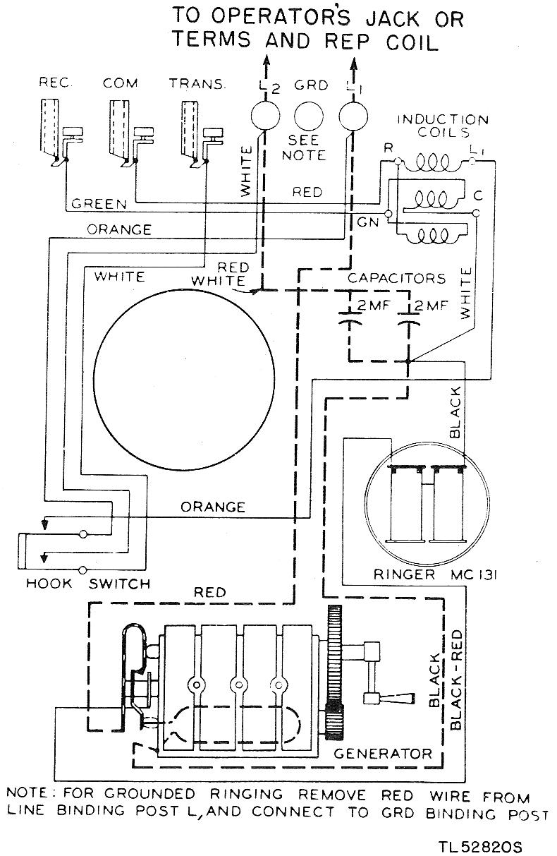
The EE-91 is a wall-mounted metal telephone box. It is a common battery phone, meaning the transmitter current is sourced from the central office battery. It features a single gong ringer and is equipped with a hand generator for...
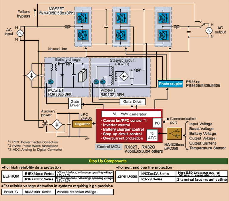
With the increasing daily reliance on networked data systems, the need for failsafe backup of power supply systems is now essential. Uninterruptible power supply (UPS) technology, characterized by a very high level of reliability, is now extensively used to...
Most telephone security devices available in the market are simple yet quite expensive. These devices typically provide blinking or beeping indications of line-tapping or misuse but often do not guarantee protection against unauthorized operations. A unique and straightforward circuit...
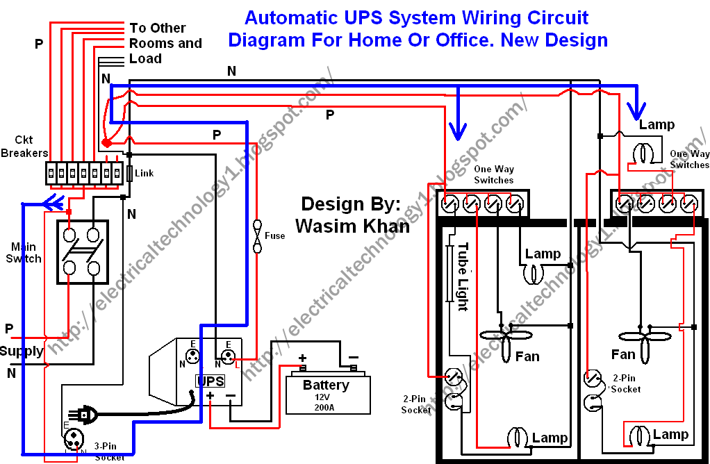
This wiring circuit diagram is designed for providing power to specific rooms in a home or office during a power supply failure. It ensures continuous power supply to devices such as laptops and computers in those particular rooms, especially...