
Automatic UPS system wiring circuit diagram (New Design Very simple) for Home or Office
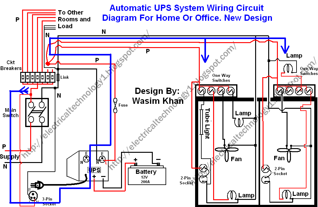
This circuit design employs a dual-source power supply system, which is essential for maintaining uninterrupted power to critical devices. The circuit is configured to automatically switch between the main power supply and the backup system (UPS or battery) without manual intervention. The inclusion of a UPS is particularly beneficial as it not only provides backup power but also conditions the power supply, protecting sensitive electronics from voltage fluctuations.
The main components of this circuit include a circuit breaker, UPS, battery, and the necessary wiring. The circuit breaker serves as the primary safety device, disconnecting the power supply in case of overload or short circuit conditions. The UPS is connected to the main distribution board, and it should be rated appropriately to handle the combined load of the devices in the connected rooms.
Wiring connections must be executed with care, ensuring that all connections are secure and insulated to prevent short circuits. The live (phase) wires removed from the circuit breaker should be routed to the input of the UPS. The output of the UPS will then be connected to the designated rooms, ensuring that power is supplied seamlessly from the main supply when available.
In cases where the main power supply is interrupted, the UPS will automatically switch to battery power, allowing devices to remain operational without any noticeable interruption. This design is particularly advantageous for environments where continuous power is critical, such as offices with computers and other electronic equipment that cannot afford downtime.
Overall, this circuit design provides a reliable solution for ensuring that essential rooms in a building maintain power continuity, effectively combining both primary and backup power sources in a streamlined manner.This wiring circuit diagram is design for when you want to give supply to particular rooms in the home or office in the building in case of failing the power supply. And you want to supply power continuously to the laptop, computer etc in that specific rooms or office in case of low wattage UPS or single battery or in case of when generator system
is not available. . First of all, remove those Live (Phase) wires from the main distribution board (from the circuit breaker) of those particular Rooms (As shown in Fig) which you want to give automatic supply (in both cases from Battery and Power House without any interrupt or disturbance). Suppose I want to connect only these two rooms with this system as shown in fig. Then connect these two live (phase) wires at the end as shown in fig. Now do the same wiring (Connect UPS, Battery, Home appliances etc) as shown in fig. Done Then power flow will continue to those particular rooms or office at this way from Power supply (Not from Battery, because when power supply available, then battery will start to charge through UPS.
🔗 External reference
Related Circuits
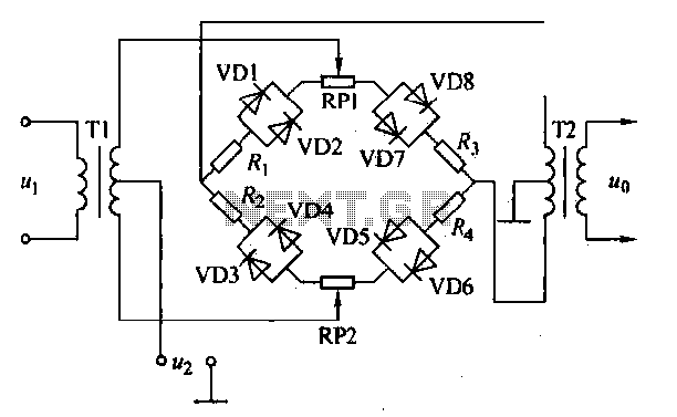
An AM diode ring circuit consists of four diodes arranged in a ring configuration, commonly referred to as a diode ring modulator circuit. This circuit offers significant advantages due to the characteristics of the diodes and the use of...
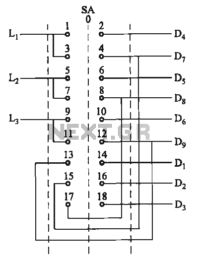
The motor switch control circuit depicted in the figure provides two speed settings for counter-steering, allowing for operation at two speeds in opposite directions. The motor switch control circuit is designed to facilitate the operation of a motor at two...
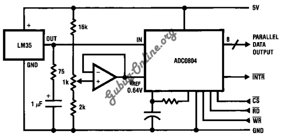
This is a design for a temperature-to-digital converter circuit that is controlled by the LM35 integrated circuit. The LM35 is a precision integrated circuit temperature sensor, whose output voltage is linearly proportional to the Celsius temperature. The circuit utilizes the...
%2Bdecoder%2BCircuit%2Bschematic%2Busing%2BM8870.png)
This DTMF (Dual Tone Multi Frequency) decoder circuit identifies the dial tone from the telephone line and decodes the key pressed on the remote telephone. For the detection of DTMF signaling, the IC MT8870DE, a touch tone decoder IC,...
Electrical equipment provided for a power supply circuit design in the power section, as illustrated below. The power supply circuit design is a critical component in various electronic systems, serving as the backbone for powering other devices. The schematic typically...
Involvement is a modified version of the classic circuit of automatic level control signal used in tape recorders. The purchase price of the components (using TL072) does not exceed CZK 60 for a channel. For a range of entry...