
UPS Power Supply
The circuit operates as a basic Uninterruptible Power Supply (UPS) designed to provide both regulated and unregulated voltage outputs. The main components include a transformer (TR1), a rectifier, a voltage regulator, and a battery backup system.
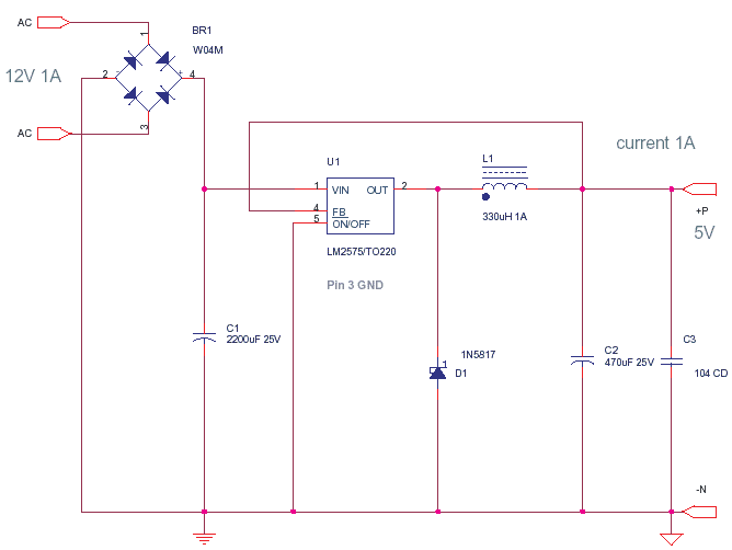
TR1 is a step-down transformer with a primary winding designed for the local electrical supply voltage, specifically rated for 240 Volts in the UK. Its secondary winding is configured to output a minimum of 12 Volts at 2 Amps, although it can be designed for higher voltages, such as 15 Volts, depending on the application requirements. The transformer’s output is connected to a rectifier circuit, which converts the AC voltage to a DC voltage suitable for battery charging and powering the load.
The circuit features a battery backup system that engages automatically during power outages. The battery, which can be selected based on the desired output voltage, ensures continuous power supply without interruption. The regulated output is achieved using a linear voltage regulator, such as the 7805 for 5 Volts or the 7815 for 15 Volts, which maintains a stable output voltage even in the event of fluctuations in the input voltage.
In terms of safety, a slow-blow fuse (FS1) is included to protect against short circuits and overcurrent situations. This fuse allows for temporary surges in current, which may occur during normal operation, but will blow if a sustained overcurrent condition arises, thereby protecting the circuit components.
The flexibility of this UPS circuit allows for customization according to the specific voltage requirements of different applications. By selecting appropriate regulators and battery configurations, users can easily adapt the circuit to meet various power supply needs. The design also emphasizes reliability, ensuring that the regulated supply remains free from voltage spikes during switchover from mains power to battery power.This circuit is a simple form of the commercial UPS, the circuit provides a constant regulated 5 Volt output and an unregulated 12 Volt supply. In the event of electrical supply line failure the battery takes over, with no spikes on the regulated supply.
This circuit can be adapted for other regulated and unregulated voltages by using different regulators and batteries. For a 15 Volt regulated supply use two 12 Volt batteries in series and a 7815 regulator. There is a lot of flexibility in this circuit. TR1 has a primary matched to the local electrical supply which is 240 Volts in the UK. The secondary winding should be rated at least 12 Volts at 2 amp, but can be higher, for example 15 Volts. FS1 is a slow blow type and protects against short circuits o 🔗 External reference
Related Circuits
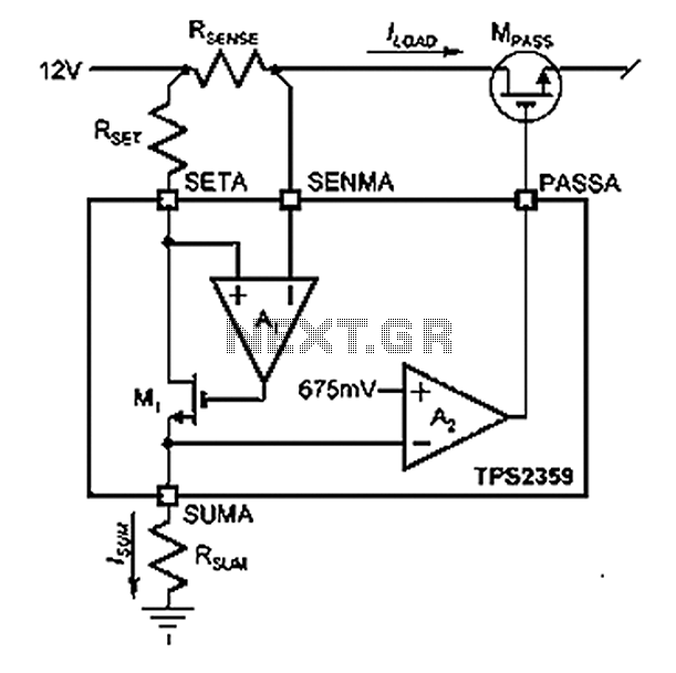
Amplifier A1 utilizes the voltage across the sense resistor sensors to monitor the load current ILOAD. The power management channel employs a similar circuit, with the distinction of integrating resistors RSENSE and RSET. Amplifier A1 is configured to measure the...
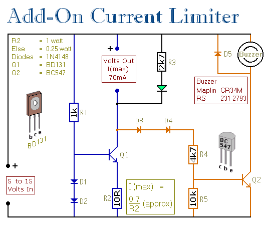
This circuit allows for setting a limit on the maximum output current from a power supply unit (PSU). It is particularly useful for initial project power-ups or during soak tests. By establishing an upper current limit, it protects both...
This battery-powered metal detector utilizes four exclusive-OR gates from the 4030 CMOS integrated circuit. The gates are configured as twin oscillators, with a search coil acting as the inductance element in one of the oscillators. When the coil approaches...
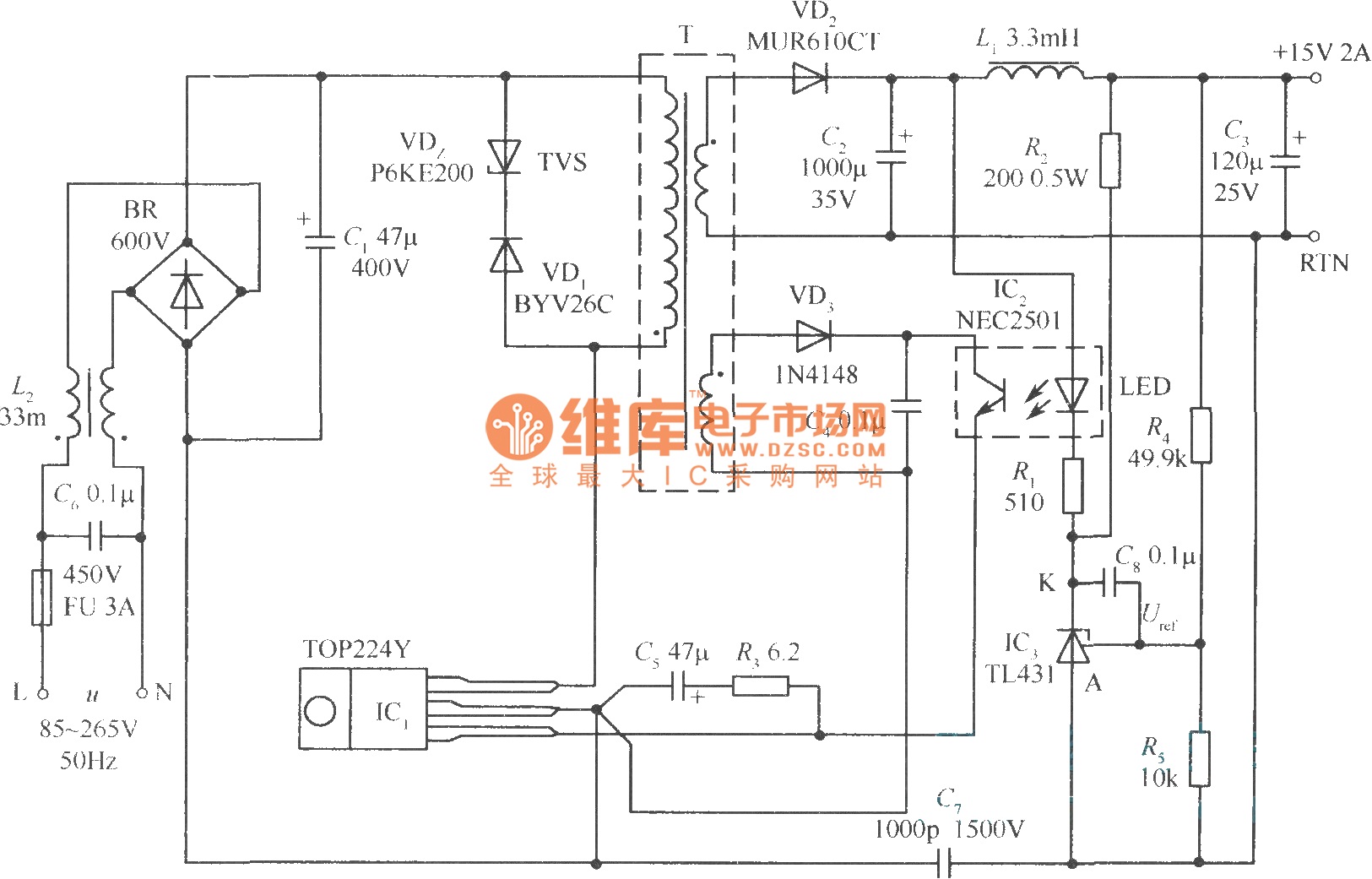
This document presents a 30W micro switch regulated power supply utilizing the TOP224Y integrated circuit. The circuit diagram illustrates its design. A notable feature of this power supply is the use of the TL431 component to replace the regulation...
This circuit generates three source-regulated voltages using a minimal number of electronic components. The output DC voltages are +12V, +5V, and -5V. Diodes D2 and D3 perform full-wave rectification while charging capacitor C2 during each half of the alternating...
A power transistor with a voltage drop of 4 volts and a current of 3 amps may dissipate approximately 12 watts of heat, presenting a challenge in series regulators. In contrast, a saturated transistor or MOSFET with a voltage...