
Multi power failure alarm circuit
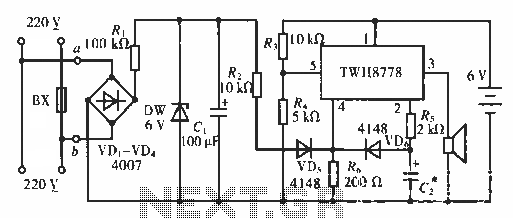
The AC blown fuse alarm circuit is designed to monitor the status of a fuse (BX) in an AC power supply system. When the fuse is intact, the circuit allows 220 V AC voltage to flow through a bridge rectifier made up of diodes VD1, VD2, VD3, and VD4. This rectification process converts the AC voltage to a pulsating DC voltage. Resistor R1 serves to limit the current entering the rectifier, protecting the circuit from potential overcurrent conditions.
Following the rectification stage, the output is fed into a voltage regulator that steps down the voltage to a stable 6 V DC. This regulated voltage is essential for powering the subsequent components in the circuit. Capacitor C1 functions as a filter, smoothing out any voltage ripples that may occur after rectification, ensuring that the voltage supplied to the rest of the circuit is steady and reliable.
Diode VD5 is implemented to isolate certain actions within the circuit, preventing interference from other components. The power switch IC TWH8778 is a critical element of the design, with pin 4 specifically designated for controlling the high power level of the circuit. When the fuse (BX) blows, the power switch IC TWH8778 is turned off, ceasing operations of the circuit. As a result, the speaker, which is intended to provide an audible alarm, remains silent, indicating that the fuse has failed.
This circuit can be utilized in various applications where monitoring of fuse integrity is necessary, providing an effective means of alerting users to potential electrical issues before they escalate. Proper implementation of components and careful consideration of voltage levels and current ratings are crucial to ensure the reliability and longevity of the circuit.Circuit works: This is an AC blown fuse alarm. When BX is not when blown, 220 V AC voltage through a VD1 VD4 bridge rectifier, R1 limiting buck, after DW 6V DC voltage regulator, C1 filter formed by R2, VD5 (isolated from the action) is applied to the power switch IC TWH8778 4 feet, 4 feet high power level, TWH8778 off does not work, the speaker does not sound.
Related Circuits

This simple square-wave generator produces a variable frequency output ranging from 2800 Hz to 80 kHz, as indicated by the specified values. The frequency can be adjusted using potentiometer R1. The square-wave generator circuit typically employs a combination of resistors,...
A switch that is controlled by its ambient temperature operates without human intervention, except during the assembly of the electronic thermostat. This thermally controlled switch has numerous practical applications. For instance, if the internal temperature of a computer rises...
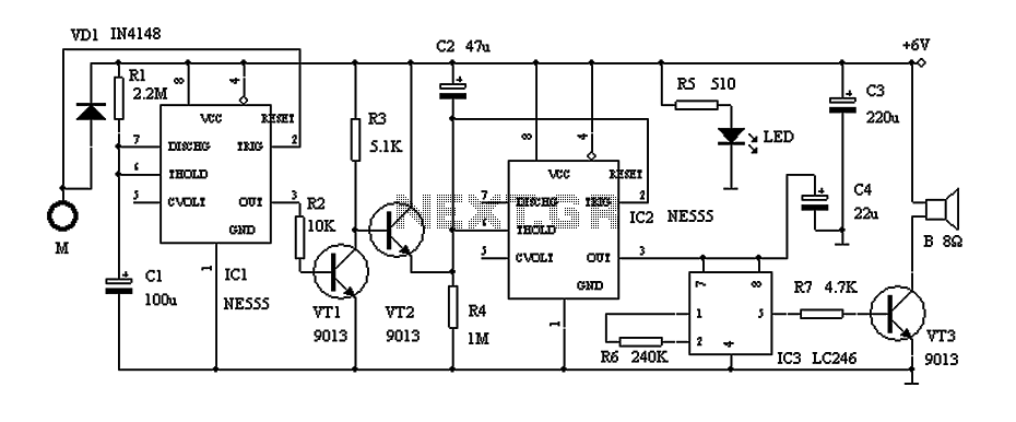
This circuit describes a door alarm system equipped with a time recognition feature. When the owner opens the door, it remains in a normal state for approximately 30 seconds without triggering the alarm. However, if the door is opened...
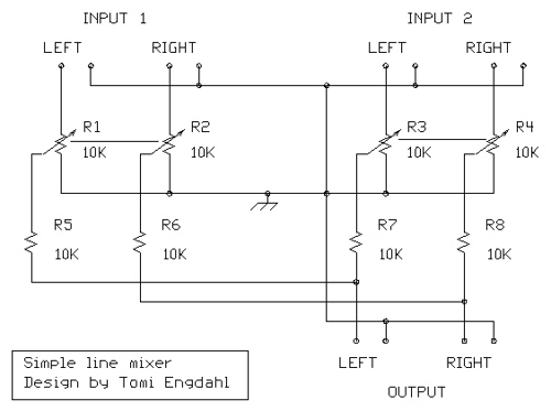
The mixer circuit described features three line inputs and three microphone inputs. The microphone inputs are designed for low impedance dynamic microphones with a range of 200 to 1000 ohms. Alternatively, an electret condenser microphone (ECM) can be used,...
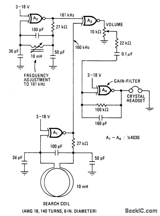
This battery-powered metal detector utilizes four exclusive-OR gates found in the 4030 CMOS integrated circuit. The gates are configured as twin oscillators, with a search coil acting as the inductance element in one of the oscillators. When the coil...
This circuit generates three source-regulated voltages using a minimal number of electronic components. The output DC voltages are +12V, +5V, and -5V. Diodes D2 and D3 perform full-wave rectification while charging capacitor C2 during each half of the alternating...