
10A stabilized power supply
The circuit described is a high-current power supply capable of delivering a stabilized output of 10A, utilizing a linear voltage regulator from the 78xx series. The 78xx series includes various voltage regulators that can provide different output voltages, thus allowing for flexibility in design based on the required output. The input voltage to the regulator must exceed the desired output voltage by a sufficient margin to ensure proper regulation.
The power handling capability of the circuit is enhanced by the inclusion of a power transistor (T1), specifically the MJ15004, which is a high-power NPN transistor. This component is crucial for managing the increased current demands and should be mounted on a substantial heat sink to dissipate heat effectively, especially under high load conditions. The heat sink is necessary to prevent thermal overload and ensure reliable operation of the circuit.
Resistors R1 and R2 are specified as 0.18 ohms with a power rating of 5W, which suggests they are likely used for current sensing or as part of a feedback loop to stabilize the output. R3, with a value of 2.2 ohms and a power rating of 2W, could be used for additional current limiting or as part of a voltage divider configuration.
Capacitors C1, C2, and C3 are integral to the circuit's performance. C1, with a capacitance of 22000 µF, acts as a bulk filter capacitor, smoothing the output voltage and providing energy storage to handle transient loads. C2 and C3, both rated at 1 µF, are likely used for high-frequency decoupling, ensuring stable operation of the regulator by filtering out noise and providing a clean power supply.
The circuit also includes a fuse (B1) rated at 35A, which serves as a protective measure against overcurrent conditions, safeguarding both the circuit and connected loads.
Overall, this heavy-duty power supply circuit is designed for applications requiring significant current, with careful consideration given to thermal management, filtering, and protection to ensure stable and reliable operation.This is a heavy diet, which can deliver 10A stabilized. The circuit is built around a normal 78xx controller, but for extra power equipped with T1. For the 78xx can be taken any type. Keep in mind that the input voltage of 3V regulator must be higher as the output nected. See 78xx power for the available controllers. T1 must be a large heat sink mounted when large capacities are diminished. A negative variant of this diet is here to find. R1, R2 = 0.18 ? 5W R3 = 2.2 ? 2W C1 = 22000?F C2, C3 = 1?F B1 = 35A T1 = MJ15004 IC1 = 78xx 🔗 External reference
Related Circuits
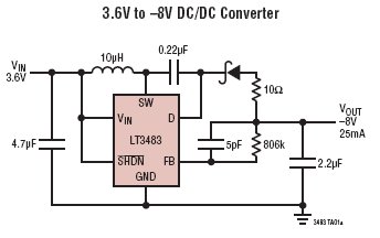
The LT3483/LT3483A are micropower inverting DC/DC converters featuring integrated Schottky diodes and a single resistor feedback mechanism. Their compact package size, high integration level, and the use of small surface mount components allow for a solution size as small...
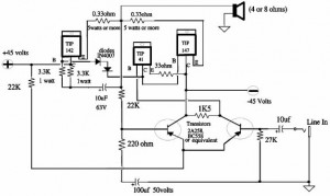
A 150W power amplifier circuit diagram utilizing power transistors TIP41, TIP142, and TIP147. The design is straightforward enough to construct without a printed circuit board (PCB). The power output range is approximately 100-150W. The 150W power amplifier circuit is designed...
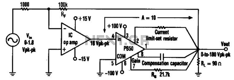
An Apex PB50 Booster Amplifier, along with an integrated circuit (IC) operational amplifier, can be utilized in a high-voltage operational amplifier configuration to convert a small analog signal into a 180-V peak-to-peak signal. Apex Microtechnology produces a variety of...
A circuit for monitoring supply voltages of ±5 V and ±12 V can be constructed as shown in the diagram. It is significantly simpler than the typical monitors that utilize comparators and AND gates. The circuit is not designed...
The purpose of a DC power supply is to deliver the necessary level of DC power to a load by utilizing an AC supply at the input. Various applications demand different specifications; however, contemporary DC power supplies often ensure...
A circuit for a bicycle horn utilizing a low-cost telecom ringer chip is presented. This design can be powered by a bicycle dynamo, eliminating the need for frequently replaced batteries. The circuit includes a half-wave voltage-doubler section formed by...