
The passive human body infrared sensor circuit
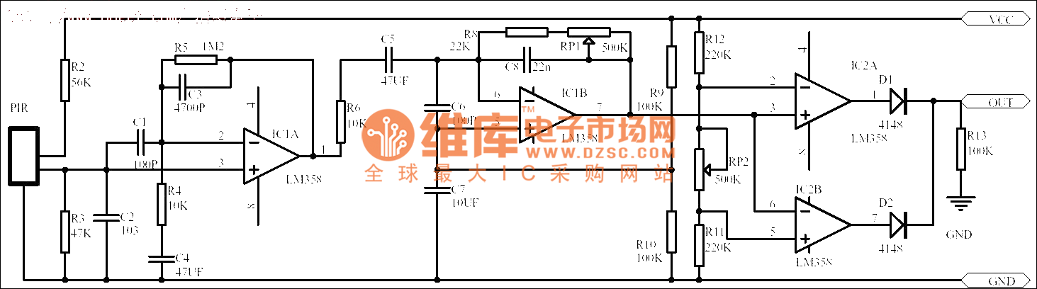
The passive human body infrared sensor circuit operates by detecting infrared radiation emitted by human bodies. This radiation is captured by the sensor, which converts it into an electrical signal. The initial stage of the circuit is crucial as it amplifies the weak signals generated by the sensor. The low-frequency signal amplifier is designed to enhance the sensitivity of the circuit, allowing it to detect subtle changes in infrared radiation.
In this particular circuit design, the amplifier's gain of 100 ensures that even minimal infrared signals are sufficiently amplified for further processing. After amplification, the signals are conditioned by passing through R6 and C5. Resistor R6 plays a critical role in setting the gain and stabilizing the amplifier, while capacitor C5 acts as a filter to eliminate high-frequency noise, ensuring that only the desired low-frequency signals within the range of 0.2 to 10 Hz are processed.
The output of this stage can then be interfaced with additional circuitry, such as signal processing units or microcontrollers, to trigger alarms, lighting systems, or other automated responses based on detected motion. The simplicity and effectiveness of this circuit make it a popular choice for various applications, including security systems, automatic lighting, and energy management systems.No matter what kind it is, passive human body infrared sensor circuits are almost the same with the above, maybe some has less stages. This circuit in the figure is got from the NICERA producer, which is classical. The stage of front-end is the low frequency signal amplifier, the magnified times are 100, then the signals pass R6 and C5 before the 0.2-10HZ s..
🔗 External reference
Related Circuits

This battery level indicator features five LEDs that illuminate progressively as the voltage increases: Red indicates power connection (0%), Yellow signifies voltage greater than 10.5V (25%). The battery level indicator circuit utilizes a series of five light-emitting diodes (LEDs) to...
The LM1036 is a DC-controlled circuit designed for adjusting tone (bass and treble), volume, and balance in stereo applications such as car radios, televisions, and audio systems. It features an additional control input for straightforward loudness compensation. The circuit...
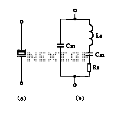
The crystal equivalent RLC circuit is illustrated. The RLC circuit can operate in either a series resonant or parallel resonant configuration. The crystal equivalent RLC circuit is a fundamental electronic circuit that models the behavior of a crystal oscillator. This...
XP power plug, FU fuse, ST temperature control, T1 low-voltage transformers, S1, S2 door interlock switch, S3 threshold control switch, RT thermal sensor, K1, K2 relay, EL furnace light, M1 wheel motor, M2 fan motor, T2 high-voltage transformer, C...
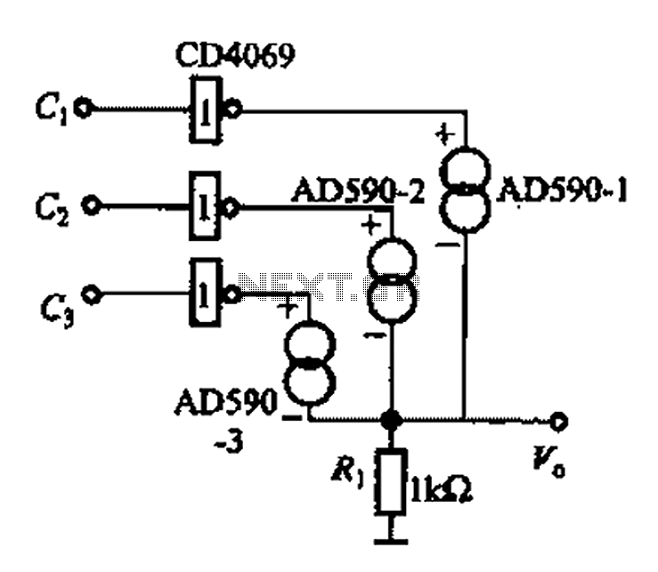
The AD590 is illustrated in a basic application circuit. As the AD590 provides a current output, a series resistance is used to convert this output current into a voltage. In the circuit, RP serves as the output voltage (vo)...

This circuit provides an intermittent siren output with an automatic reset feature. It can be operated manually through a key-switch or a hidden switch, and it can also be configured to activate automatically when the ignition is turned off....