
ssl3250a photo flash led driver circuit

The SSL3250A is a versatile integrated circuit designed for LED driving applications, particularly in portable devices. It operates over a wide input voltage range, making it suitable for various battery types and configurations. The ability to deliver a large maximum output current ensures that it can drive high-brightness LEDs effectively, which is crucial for applications requiring significant illumination, such as camera flash or torch functionalities.
The high efficiency of the SSL3250A is a key feature, as it minimizes power loss during operation, contributing to extended battery life. The soft-start functionality is particularly important in preventing sudden current surges that could damage the LED or the power source. This gradual ramp-up of current helps to ensure a smooth operation, particularly in sensitive applications.
In terms of protection features, the SSL3250A is equipped with several mechanisms to enhance reliability. Overvoltage protection prevents damage to the LED and the circuit in scenarios where the input voltage exceeds safe levels. Over-temperature protection ensures that the device operates within safe thermal limits, which is critical for maintaining performance and longevity. Feedback short protection and under-voltage lockout features further enhance the robustness of the design, preventing operational failures under adverse conditions.
The dual control modes—Direct and I2C—provide flexibility in how the SSL3250A can be integrated into a system. Direct control mode allows for straightforward implementation, where the device can be controlled using simple enable signals (EN1 and EN2). This mode is ideal for applications that require minimal complexity and quick response times.
On the other hand, I2C control mode offers advanced configurability, allowing for dynamic adjustments to timing and current settings. This mode is particularly beneficial in applications where different LED modes (Flash, Torch, Indicator) are required, enabling a single device to serve multiple functions based on the operational context. The use of I2C communication facilitates easy integration into microcontroller-based systems, allowing for more sophisticated control schemes.
Overall, the SSL3250A is designed to meet the demands of modern mobile applications, combining efficiency, protection, and versatile control options to ensure optimal performance in LED driving tasks.This device ensure a lot of implementation possibilities because it has wide input voltage range and the large maximum output current at a wide output voltage range. It has long battery life and low power strain because of it`s high efficiency and soft-start. This device has many features which is can be used to protect the battery and LED from ov erloading, and result in trouble-free operation of the whole mobile application such as overvoltage, over temperature and feedback shorted protection, under voltage lockout and time-out function. This is the figure of the circuit; This device (SSL3250A) has two general control modes: Direct control (the lower circuit schematic diagram) and I2C Control (the upper circuit schematic diagram).
The IC is designed to be directly controlled by the application in direct control mode. To change the timing and current settings of the SSL3250A, we can use I2C control. We can also use I2C control to switch the driver to Flash mode, Torch mode or Indicator mode. EN1 and EN2 are used in Direct control mode. SCL, SDA, and STRB are used in I2C control mode. In a typical application, we only allowed to use one control mode. 🔗 External reference
Related Circuits
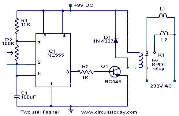
A circuit designed to alternately flash two Christmas stars is presented. The NE555 integrated circuit (IC1) is configured as an astable multivibrator. When IC1 outputs a positive pulse, transistor Q1 becomes conductive, activating relay K1. Consequently, lamp L2, connected...
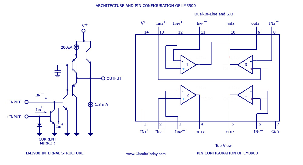
A simple multi-channel audio mixer circuit utilizing the LM3900 quad amplifier is presented below. The circuit features a four-channel quad amplifier (LM3900) with two microphone audio inputs and two direct line inputs. By paralleling additional circuits, the number of...
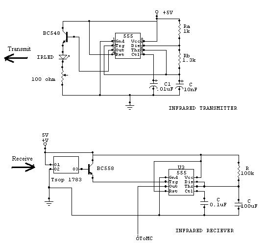
The two circuits below illustrate the application of the 555 timer to activate a relay for a specified duration by pressing a momentary normally open (N/O) push button. The circuit on the left can be used for longer time...
For a robot to perform its assigned tasks, a controller is necessary. This controller may be mechanical, electrical, electronic, or a combination of these. It acts as the brain of the entire system, providing the robot with its intelligence....

The TDA7262 integrated circuit, manufactured by ST Microelectronics, can be utilized to design a straightforward stereo audio amplifier project. This circuit can deliver a maximum output power of 20 watts per channel. The TDA7262 is a dual Hi-Fi audio...
Here is a deluxe version of the simple charge rate limiter, using the same idea but with the ability to charge two packs simultaneously from a single wall charger. For circuit description and parts list, see the simple charger...