
circuit 10a variable power supply symmetric

The 10A variable power supply circuit is designed to meet the needs of various electronic applications requiring adjustable voltage and current. The symmetrical design allows for both positive and negative voltage outputs, making it suitable for dual-polarity operations in experimental setups. The LM317 and LM337 regulators are well-regarded for their reliability and performance in voltage regulation, providing stable outputs despite variations in load conditions.
The full-wave rectifier bridge converts the AC voltage from the transformer into a pulsating DC voltage, which is then smoothed by the large filter capacitor. This capacitor is critical in minimizing voltage ripple, ensuring that the output voltage remains stable during operation. The use of a 10,000µF capacitor is significant, as it provides substantial energy storage, allowing the circuit to maintain output stability under load transients.
The potentiometers used for voltage adjustment enable fine-tuning of the output voltage, allowing users to set precise voltage levels as required for their applications. The common base configuration of the TIP147 and TIP142 transistors enhances the circuit's ability to drive higher currents while maintaining stability and reducing distortion.
Incorporating short circuit and overheat protection mechanisms is essential for the longevity and safety of the power supply circuit. These features help prevent damage to the circuit components in the event of a fault condition, ensuring safe operation under various load scenarios. Overall, this 10A variable power supply circuit is a robust solution for laboratory experiments and other applications that demand flexible power supply options.10A variable power supply circuit is symmetrical in the figure below, can provide symmetrical output voltage of ± 1. 2 volts to ± 30 volts DC with a current maximum of 10A. 10A variable power supply circuit uses symmetrical variable voltage regulator LM317 and LM337 then using a current amplifier transistor NPN and PNP transistors TIP147 TIP142 i
s able to drain currents up to 10 amperes. Power supply circuit equipped with a list of components can be seen in Figure 10A variable power supply circuit following symmetrical. Above the power supply circuit using a 32 volt CT transformer 10A and diode full-wave rectifier bridge as symmetric then use the filter capacitor riple 10000uF / 40V.
As a positive voltage regulator using LM317 IC which can control a stable voltage of 1. 2 volts DC to 30 volts DC. Positive output voltage regulator using 2. 2 Kohm potentiometer and a positive path current amplifier using TIP147 PNP transistor is coupled common base. Section a negative power supply voltage using a variable voltage regulator IC LM337 which is controlled using 2.
2 Kohm potentiometer in order to provide a negative output voltage of -1. 2 volts DC to -30 volts DC. Negative path current amplifier using TIP142 NPN transistor is coupled common base. Variable power supply circuit 10A is suitable for use on a symmetric space experiments as giving a voltage source which can diatus as needed to complete the polarity selection and are able to supply DC currents up to 10A. Power supply circuit is equipped with short circuit protection (short circuit) and excessive heat (over heat) on the variable power supply circuit 10A are symmetrical.
🔗 External reference
Related Circuits
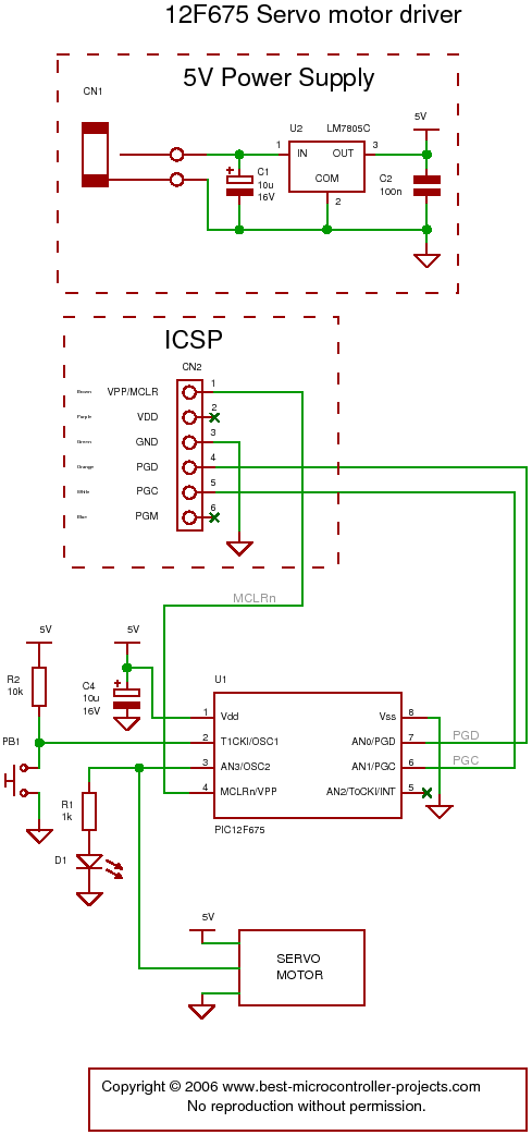
The following circuit illustrates a servo motor driver. This circuit is based on the 12F675 IC. Features include Timer 0 timing and a single control line. The servo motor driver circuit utilizing the 12F675 integrated circuit (IC) is designed to...
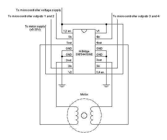
A stepper motor is a motor controlled by a series of electromagnetic coils. The center shaft has a series of magnets mounted on it, and the coils surrounding the shaft are alternately energized or de-energized, creating magnetic fields that...
The paraphase configuration is noteworthy for its ability to adjust either treble or bass, but not both simultaneously. The adjustments made to the tone controls directly influence the slope of the frequency response and the extent of bass and...
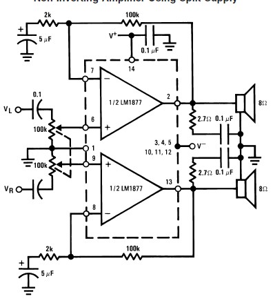
This audio amplifier circuit is designed to deliver 2W per channel continuously into 8-ohm loads. The LM1877 is engineered to function with a minimal number of external components while still offering flexibility for applications in stereo phonographs, tape recorders,...
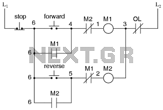
This is the power diagram for motor forward and reverse operation. To change the motor direction, one polarity must be altered, for example, changing R to S. For detailed information, please refer to the following. The described power diagram illustrates...
An FM radio generates an interference signal that can be detected on another FM radio tuned 10.7 MHz higher than the original. A 50 kΩ potentiometer is used to adjust the modulation level to its maximum without introducing distortion....