
USB car charger circuit

The USB car charger circuit typically consists of several key components to ensure efficient voltage conversion and regulation. The primary component is a step-down (buck) converter, which reduces the input voltage from 12V to 5V. This converter may utilize a switching regulator to improve efficiency and minimize heat generation during operation.
Additional components include input and output capacitors to filter voltage spikes and provide stability. A diode may be included to prevent reverse polarity, ensuring that the circuit only operates when the correct voltage is supplied. Furthermore, a microcontroller or dedicated voltage regulator IC can be integrated to manage output voltage levels and provide overcurrent protection.
The circuit is designed to be compact, allowing it to fit within the confines of a standard USB car charger casing. Proper heat dissipation methods, such as heatsinks or thermal pads, may be implemented to maintain optimal operating temperatures during prolonged usage. This design enables the charger to safely power various devices, including smartphones, tablets, and other USB-powered gadgets, while ensuring reliable performance in a vehicle environment.This USB car charger circuit adapter from car cigar socket project is a DC DC power converter that safely converts the 12V car battery voltage into stable 5V. This circuit can be used to supply power from a car cigar lighter socket to a por.. 🔗 External reference
Related Circuits
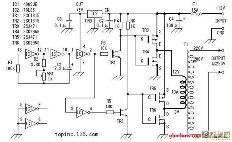
The inverter described in this text utilizes a MOS field-effect transistor and a standard power transformer. Its output power is determined by the capabilities of both the MOS field-effect transistor and the transformer, eliminating the need for complex voltage...
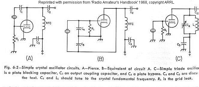
The frequency of a crystal-controlled oscillator is maintained with high precision through the use of a quartz crystal. The frequency is primarily determined by the dimensions of the crystal, particularly its thickness, while other circuit parameters have minimal impact....
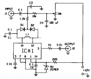
The FM modulator circuit, which utilizes frequency modulation, is constructed with a Motorola MC1648P oscillator. It employs two varactors, specifically Motorola MV-209, to achieve frequency modulation of the oscillator. A 5000 Ω potentiometer is incorporated to bias the varactors...
This simple circuit tests speakers, microphones, transformers, and voltage. It is essentially a very low-frequency oscillator that produces extremely short "fruity" pulses. The sound produced is easy to hear and allows for precise determination of its direction, making it...
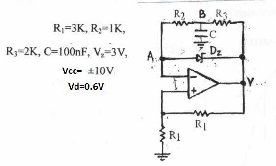
This circuit appears to be a Schmitt trigger oscillator. Based on the configuration of the resistors and capacitor, it is likely functioning as a sawtooth wave generator, with resistors R2 and R3 influencing the slope of the rising and...
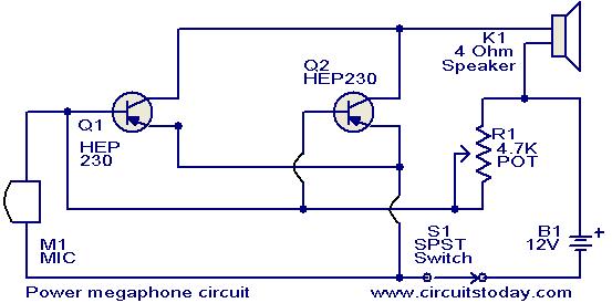
Any power transistor can be used in this megaphone, which is suitable for boats, playing fields, and similar applications. The transistors Q1 and Q2 are of the HEP-230 type, which are readily available in the market. These transistors are...