
Crystal-Oscillator Circuits

The crystal-controlled oscillator is a critical component in various electronic applications, providing stable frequency generation essential for communication systems, signal processing, and timing circuits. The design typically involves a feedback mechanism that utilizes the properties of the quartz crystal to maintain oscillation at a specific frequency. The oscillator circuit's stability and performance can be influenced by various factors, including the choice of active components, the configuration of the feedback network, and the quality of the crystal itself.
In practical implementations, the oscillator may be designed to operate within specific frequency ranges, necessitating careful selection of passive components such as capacitors and inductors to achieve the desired tuning characteristics. The use of external capacitors, as mentioned, enhances the control over excitation levels and overall circuit performance. Additionally, the integration of amplifying stages can significantly improve output power, allowing the oscillator to drive larger loads or interface with subsequent circuit stages effectively.
Thermal management is also an important consideration in the design of crystal oscillators. Excessive heating can lead to frequency instability and potential damage to the crystal. Therefore, implementing feedback mechanisms that minimize crystal current while maintaining sufficient excitation for stable oscillation is crucial. This balance can be achieved through careful circuit design, including the use of variable resistors or capacitors to fine-tune the excitation levels dynamically.
Overall, crystal-controlled oscillators represent a foundational technology in electronics, with their precise frequency control enabling advancements across various fields, including telecommunications, instrumentation, and consumer electronics. Proper understanding and implementation of these circuits are essential for engineers and designers aiming to create reliable and efficient electronic systems.The frequency of a crystal-controlled oscillator is held constant to a high degree of accuracy by the use of a quartz crystal. The frequency depends almost entirely on the dimensions of the crystal (essentially its thickness); other circuit values have comparatively negligible effect.
However, the power obtainable is limited by the heat the crysta l will stand without fracturing. The amount of heating is dependent upon the r. f. crystal current which, in turn, is a function of the amount of feedback required to provide proper excitation. Crystal heating short of the danger point results in frequency drift to an extent depending upon the way the crystal is cut.
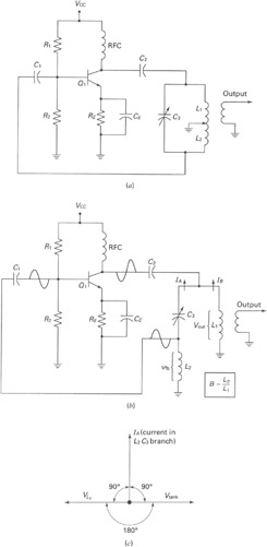
Excitation should always be adjusted to the minimum necessary for proper operation. The simplest crystal-oscillator circuit is shown in Fig. 6-2A. An equivalent circuit is shown in Fig. 6-2B. , where C4 represents the grid -cathode capacitance and C5 indicates the plate-cathode, or output capacitance. The ratio of these capacitors controls the excitation for the oscillator, and good practice generally requires that both of these capacitances be augmented by external capacitors, to provide better control of the excitation.
The circuit shown in Fig. 6-2C is the equivalent of the tuned-grid tuned-plate circuit discussed in the chapter on vacuum-tube principles, the crystal replacing the tuned grid circuit. The most commonly used crystal-oscillator circuits are based on one or the other of these two simple types, and are shown in Fig.
6-3. Although these circuits are somewhat more complicated, they combine the functions of oscillator and amplifier or frequency multiplier in a single tube. In all of these circuits, the screen of the tetrode or pentode is used as the plate in a triode oscillator.
Power output is taken from a separate tuned tank circuit in the actual plate circuit. Although the oscillator itself is not entirely independent of adjustments made in the plate tank circuit when the latter is tuned near the fundamental frequency of the crystal, the effects can be satisfactorily minimized by proper choice of the oscillator tube. The circuit of Fig. 6-3 is known as the Tritet. The oscillator circuit is that of Fig. 6-2C. Excitation is controlled by adjustment of the L1C1, which should have a low L/C ratio, and be tuned considerably to the high-frequency side of the crystal frequency (approximately 5-Mc.
for a 3. 5-Mc. crystal) to prevent over-excitation and high crystal current. Once the proper adjustment for average crystals has been found, C1 may be replaced with a fixed capacitor of equal value. The oscillator of the grid-plate circuit of Fig. 6-3C is the same as that of Fig. 6-3B, except that the ground point has been moved from the cathode to the plate of the oscillator (in other words, to the screen of the tube).
Excitation is adjusted by proper proportioning of C6 and C7. When most types of tubes are used in the circuits of Fig. 6-3, oscillation will stop when the output plate circuit is tuned to the crystal frequency, and it is necessary to operate with the plate tank circuit critically detuned for maximum output with stability. However, when the 6AG7, 5763, or the lower-power 6AH6 is used with proper adjustment of excitation, it is possible to tune to the crystal frequency without stopping oscillation.
The plate tuning characteristic should then be similar to Fig. 6-4. These tubes also operate with less crystal current than most other types for a given power output, and less frequency change occurs when the plate circuit is tuned through the crystal frequency (less than 25 cycles at 3. 5 Mc. ). Crystal current may be estimated by observing the relative brilliance of a 60-ma. dial lamp connected in series with the crystal. Current should be held to a minimum for satisfactory output by careful adjustment of excitation. With the operating voltages shown, satisfactory output should be obtained with cry 🔗 External reference
Related Circuits
A widely recognized circuit is the Hartley oscillator, which is characterized by a tapped coil within the LC tank circuit. The tap point of the coil is grounded. The oscillator's amplifier section functions as a common-emitter amplifier, resulting in...
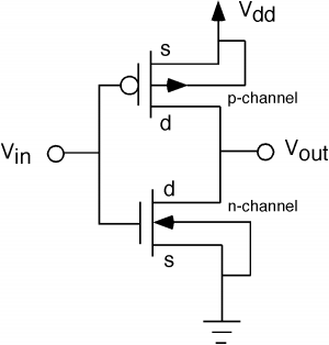
The fundamental issue presented is the perception that logic gates in a circuit seem to generate power from nothing, which contradicts the principles of physics. For instance, consider two NOT gates connected in series. It appears that the first...
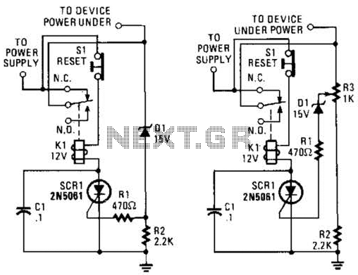
If circuits experience frequency overvoltage conditions, continually replacing blown fuses can become quite costly. This shutdown circuit addresses that issue by substituting the fuse with a relay and a low-current SCR. When the input voltage exceeds the threshold established...
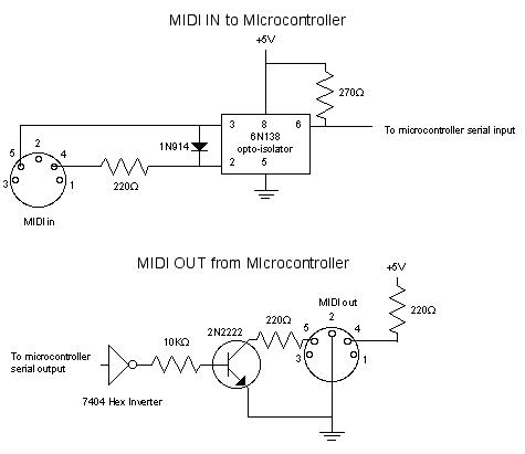
MIDI, or Musical Instrument Digital Interface, is a specification for a communications protocol between digital synthesizers and other digital music devices. It was developed to be as simple and general as possible, providing synthesizer manufacturers with significant flexibility while...
The PT2399 digital echo circuit schematic is an electronic design that utilizes the PT2399 integrated circuit (IC) for audio applications. This digital echo processor, based on CMOS technology, incorporates both analog-to-digital conversion (ADC) and digital-to-analog conversion (DAC) processes for...

To prevent deep discharge that can damage or shorten the life of a rechargeable battery, it is essential to disconnect its load before the battery is completely discharged. The circuit protects against AC line disturbances by switching off the...