
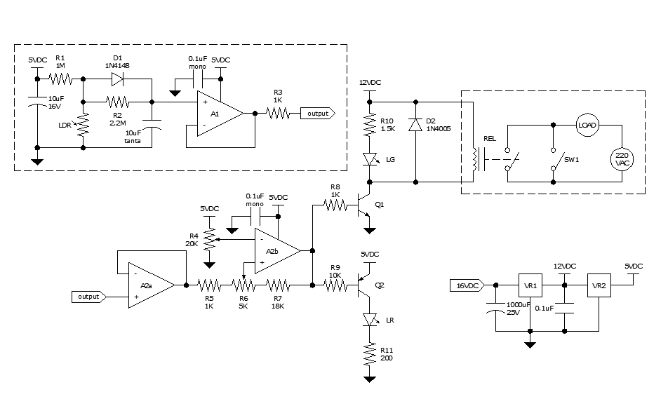
oscillator circuit with opamp and zener diode
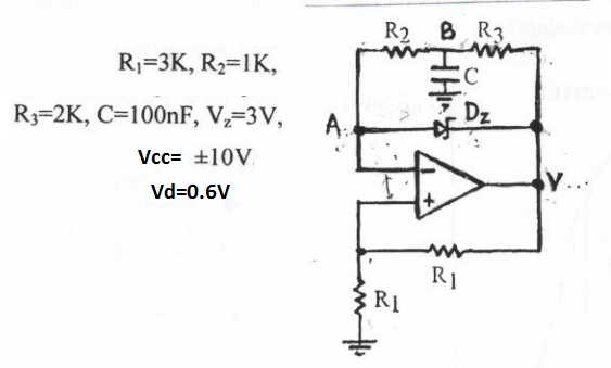
The circuit utilizes a Schmitt trigger, which is known for its ability to provide hysteresis in the input signal, allowing for clean transitions between high and low states. The sawtooth wave generator aspect is achieved through the charging and discharging of a capacitor, which is influenced by the resistors R2 and R3. The values of these resistors determine the rate at which the capacitor charges and discharges, thereby affecting the frequency and duty cycle of the output waveform.
The Zener diode plays a crucial role in this configuration. By clamping the voltage at a specified level, it ensures that the output does not exceed a certain amplitude, thereby protecting downstream components from potential damage due to overvoltage. If the Zener diode is indeed truncating the waveform, it modifies the output from a pure sawtooth to a trapezoidal shape, which may be beneficial in applications requiring a more controlled voltage profile.
In practical applications, this type of oscillator can be used in signal generation, timing circuits, and waveform shaping. The precise control over the output waveform characteristics makes it suitable for various electronic applications, including audio synthesis and modulation. The design's simplicity and effectiveness make it an excellent choice for engineers looking to implement a reliable waveform generator in their projects.Looks like a schmitt trigger oscillator. By the way the resistors and capacitor are used it is probably a saw-tooth wave generator with R2 & R3 determining the slope of the rising and trailing edges. The zener helps control the amplitude between 0 to 3V OR maybe it chops off the tops of the sawtooth wave thereby creating an output that has a trapezoidal waveform.
🔗 External reference
Related Circuits
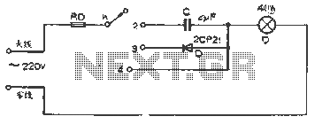
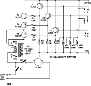
The figure illustrates a basic dimming lights circuit. The light intensity is controlled by a multi-speed control switch, designated as K. When switch K is set to position "1," the lights are turned off. In position "2," the light...
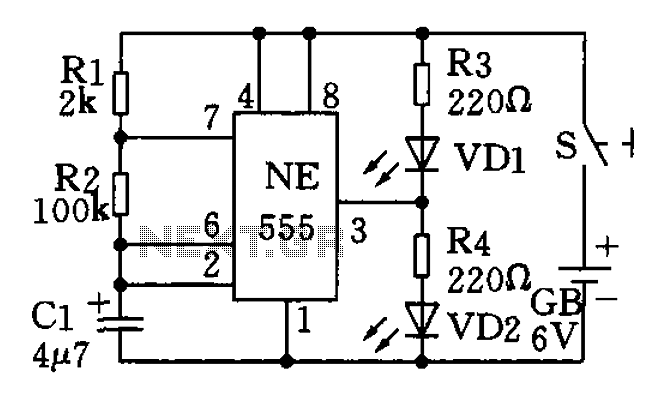
The circuit utilizes a 555 timer as the central component of a flashing light circuit. In normal operation, the light-emitting diodes (LEDs) VD1 and VD2 alternate flashing. The circuit comprises the NE555 timer, resistors R1 and R2, and capacitor...
The chip in the center with small bullet holes is likely proprietary. It is possible to salvage a few components from it, although understanding the circuit is not necessary for this purpose. Additionally, it is confirmed that the device...
Approximately ten days ago, an all-linear automatic night light circuit was installed to control the lights in the living room. The circuit comprises three operational amplifiers (op-amps): two configured as voltage followers and one as a comparator. As depicted...
This simple water detector circuit utilizes alternating voltage to prevent the corrosion of the electrodes. It is straightforward to construct and employs N1 as a trigger Schmitt gate that generates the AC signal. When an electrical conductor, such as...
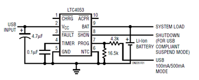
The schematic presented illustrates a minimal component solution for a USB battery charger utilizing the LTC4053 integrated circuit (IC) to create a fully compliant USB charger. This IC functions as a standalone linear charger designed for lithium-ion (Li-ion) batteries,...