
Design Parallel Port Interface Project PCB
The Parallel Port Interface Circuit utilizing the 74HCT373 is designed to facilitate high-speed data transmission and control for various output devices. The 74HCT373 is a versatile latching buffer capable of holding data stable while it is being processed by connected devices. In this configuration, it can effectively manage large arrays of relays and LEDs, making it suitable for applications such as automation, display technology, and control systems.
The circuit operates by latching the data into the 74HCT373 when a specific output device is selected. This selection process is achieved through the use of decoders, which interpret the control signals from the microcontroller or computer. The output from the decoders determines which device is active at any given time, ensuring that only one device is driven at a time to avoid signal conflicts.
The design allows for flexibility in terms of output configuration, supporting both static and dynamic outputs. For static applications, the circuit can maintain a constant output state, while for dynamic applications, it can generate waveforms or other varying signals. The ability to operate in different bit modes (8-bit, 16-bit, 32-bit) further enhances the circuit's utility, allowing it to adapt to various data throughput requirements.
To ensure optimal performance, careful attention should be given to the power supply and grounding of the circuit, as well as the selection of appropriate components that match the desired operating conditions. The integration of HCT technology provides an advantage in terms of speed and power efficiency, making it a suitable choice for modern electronic applications where space and power consumption are critical factors.
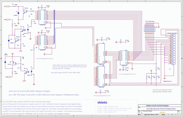
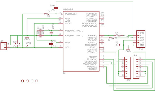
Overall, this Parallel Port Interface Circuit represents a robust solution for controlling multiple output devices, leveraging the capabilities of the 74HCT373 to provide reliable and efficient operation in a variety of electronic systems.Circuit The following schematic shows the design of a Parallel Port Interface Circuit Diagram using 74HCT373. The 74HC/HCT373 are high-speed Si-gate CMOS devices and are pin compatible with low power Schottky TTL (LSTTL).
This parallel port interface circuit design could drive 256 Relays or 16K LEDs as Dot Matrix display. It can be used to drive a Large size multiplexed LED dot matrix display or Latched Relay-Solenoid-Motor-Lamp Array Drivers. Using this circuit on Printer Port, one could drive 256 Relays or 16K LEDs as Dot Matrix display. It can be used to drive a Large size multiplexed LED dot matrix display or Latched Relay-Solenoid-Motor-Lamp Array Drivers. This circuit can be modified for a Static drive output or a fast changing output like a Waveform Generator.
You can also make it a 16 Bit waveform generator. The frequency limited to the speed of the port or a fraction of it, depending on 8bit, 16bit or 32bit. Now I have Some Explaining to do. Latch the U7 with a 8 Bit Data to address the device you want to talk to. So one among the 32 Output Devices can be Selected by a combination of G1-G2 of U5-U8 and U7 8 Bits, Split into Two Nibbles for Upper and Lower 16 Devices.
That means 16 * 2 = 32 Devices of 1 Byte each, . 32 * 8 = 256 if my calculations are correct. Please verify. One of the decoders U5 or U8 decode their respective nibble and output a Low on Selected device to Latch Data on the Chosen one (74HCT373). Why HCT Speed is good, low power and CMOS ! and works with TTL too. It Interfaced well for me on a Card with Both TTL and CMOS levels, with a Fast uC. To view the circuit below, Click the Link of PNG or PDF and view the Circuit, PNG can be Scrolled with Mouse and PDF can be Viewed-Zoomed in the Browsers with Acrobat plugin.
The Javascript and Images must be enabled in your Browser. 🔗 External reference
Related Circuits
TL072 is a low-noise JFET input operational amplifier characterized by features such as a common-mode input voltage range, high slew rate, operation without latch-up, compensated internal frequency, high input impedance at the JFET input stage, low noise, low total...
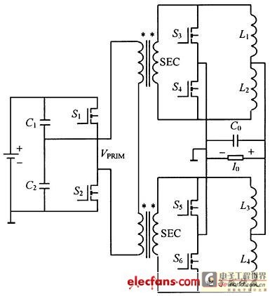
This structure significantly reduces electric current ripple on the filtering capacitance, thereby minimizing the inductive magnitude and overall size of the DC-DC converter. The converter operates at a switching frequency of 100 kHz with an input voltage of 48V....
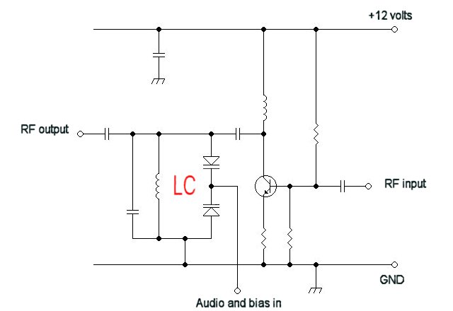
For a fixed frequency transmitter, a common method is to use a resonant quartz crystal in a crystal oscillator to establish the frequency. In transmitters where the frequency must be variable, several options are available. It is often the...
This text assumes some prior knowledge of PCB etching methods and recounts an experience with the toner transfer technique. For those unfamiliar with the method, additional research may be necessary. The process of constructing a circuit on protoboard is...
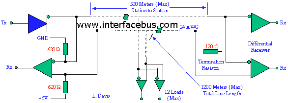
EIA/TIA-422 defines a balanced (differential) interface, specifying a single, unidirectional driver with multiple receivers (up to 32). RS-422 supports point-to-point and multi-drop circuits but not multi-point circuits (EIA-485). EIA-485 devices may be used in 422 circuits, but EIA-422 cannot...
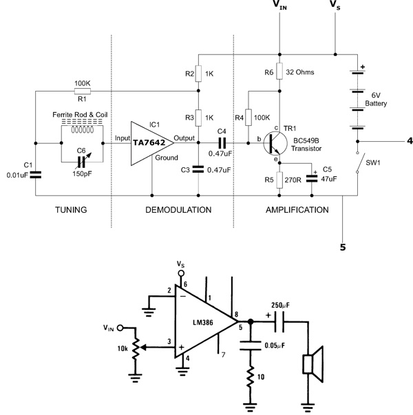
This functioning radio was built for an electronics module. The specified design was modified to include batteries, a switch, and a speaker instead of headphones. An additional amplifier circuit was required to power the speaker driver. Although not necessary,...
Warning: include(partials/cookie-banner.php): Failed to open stream: Permission denied in /var/www/html/nextgr/view-circuit.php on line 713
Warning: include(): Failed opening 'partials/cookie-banner.php' for inclusion (include_path='.:/usr/share/php') in /var/www/html/nextgr/view-circuit.php on line 713