
USB Joystick
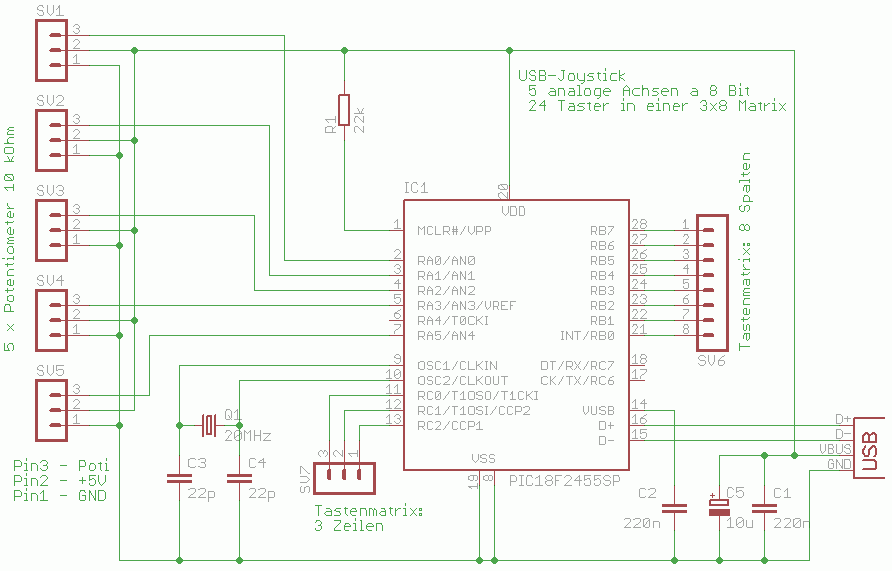
The joystick controller design leverages the capabilities of the PIC18F2455 microcontroller, which features sufficient input/output ports to manage the required axes and buttons. This microcontroller is well-suited for handling multiple analog inputs from potentiometers and digital inputs from push buttons. The USB interface allows for direct connection to a PC, facilitating easy integration without the need for additional drivers, as it adheres to the USB Human Interface Device (HID) class specifications.
The circuit should incorporate a robust power management system to ensure stable operation during extended use. The choice of capacitors is critical; C1 and C5 should be selected to handle the expected load and provide adequate filtering to prevent voltage fluctuations that could affect performance. C2's role in stabilizing the USB voltage is vital for maintaining the integrity of the microcontroller's operation.
For the potentiometer connections, each of the five axes can be controlled by a linear potentiometer, which translates the physical movement into an electrical signal that the microcontroller can interpret. The non-critical nature of the resistivity value allows for flexibility in component selection, enabling hobbyists to source readily available potentiometers. The wiper connection to pin 3 of the connector is essential, as it provides the variable voltage input to the microcontroller corresponding to the position of the joystick.
In summary, this joystick controller project presents a comprehensive solution for enthusiasts looking to enhance their flight simulation experience. By utilizing the PIC18F2455 microcontroller and a well-thought-out circuit design, users can create a highly functional and customizable joystick controller that seamlessly integrates with modern PC systems.It makes sense to build your own individual joystick. Especially the flight simulation enthusiasts like to build cockpit parts with the look and feel of original aircraft parts. Such self made hardware needs an joystick controller that meets the requirements of the hobbyists. This project is ideal to build up devices with up to 5 axi s and 24 buttons. It is based on the microcontroller PIC18F2455. I was inspired by a project on opencockpits. com. There is used the outdated PIC16C745 to design a similar project. The operating system of any modern PC recognizes the device as a joystick with 3 additional axis (sums up to 5 axis) and 24 buttons, not needing additional software or driver. The joystick-controller is powered and controlled via USB. The capacitors C1 and C5 stabilize the supply voltage. C2 is stabilizing the USB-voltage if the internal 3. 3V-voltage regulator. To every 3-pin-connector SV1 bis SV5 can be hooked up a linear 10-kOhm-potentiometer (the resistivity value is non critical).
The sliding contact of the potentiometer has to be connected to pin 3 of the connector. 🔗 External reference
Related Circuits
This document outlines a project completed by a team between September 2000 and March 2001 as part of the Engineering Physics degree program at the University of British Columbia. The project involved constructing a USB device utilizing the PIC...
Lithium Polymer Batteries are a very common source of power today. Many electronics gadgets have one inside, and they have some reasonable features. I've bought great batteries, with different sizes and capacities for my electronics projects. So long I'm...
This USB to Serial RS232 adapter is highly beneficial in scenarios where a device with RS232 needs to be connected to a computer lacking an RS232 port but equipped with a USB port. Utilizing the FT232BM chip produced by...
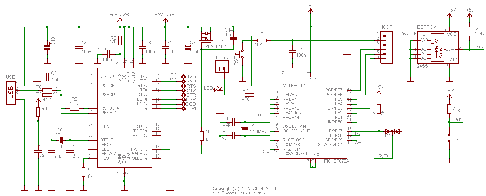
28-pin development board featuring an integrated USB connection. Power and serial communication are facilitated by the FTDI USB to RS232 converter chip. No additional setup is required; simply connect the USB. This 28-pin development board is designed for ease of...
The enable signal for the USB chip and GLCD controller is generated by a PLD decoder from the address lines. The memory map for the I/O of the 8051SBC board indicates that the available space ranges from 0x0300 to...
GTP USB PIC Programmer (Open Source). This project includes the GTP USB (not plus or lite). The schematic, photos, and PCB have been developed by PICMASTERS. The GTP USB PIC Programmer is an open-source device designed for programming PIC microcontrollers...