
gtp usb pic programmer open source using pic18f252
The GTP USB PIC Programmer is an open-source device designed for programming PIC microcontrollers via USB. It is important to note that this version is the standard GTP USB model, distinguishing it from the GTP USB Plus and Lite variants. The project is characterized by its accessible design, allowing users to replicate the hardware and software components.
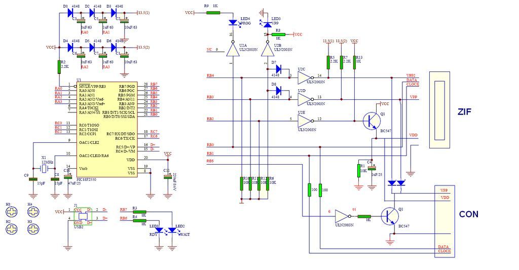
The schematic diagram of the GTP USB PIC Programmer illustrates the interconnections between the various components, including the microcontroller, voltage regulators, and USB interface circuitry. The design typically incorporates a PIC microcontroller that manages the programming operations, interfacing with the target PIC microcontroller through a set of programming pins. The USB interface allows for easy connection to a computer, enabling the transfer of programming data.
The PCB layout is optimized for compactness and efficiency, ensuring that all components are placed in a manner that minimizes interference and maximizes signal integrity. The board is designed to accommodate standard USB connections and includes necessary decoupling capacitors to stabilize the power supply.
Photos accompanying the project provide visual references for assembly and component placement, aiding users in building their own programmers. The open-source nature of this project encourages community contributions, allowing for improvements and modifications to enhance functionality or compatibility with a broader range of PIC microcontrollers.
In summary, the GTP USB PIC Programmer represents a valuable tool for hobbyists and professionals alike, facilitating the programming of PIC microcontrollers in a user-friendly manner while promoting an open-source ethos within the electronics community.GTP USB PIC PROGRAMMER (Open Source) This work includes, GTP USB (not plus or lite) . The schematic, photos and PCB have been developed by PICMASTERS based.. 🔗 External reference
Related Circuits
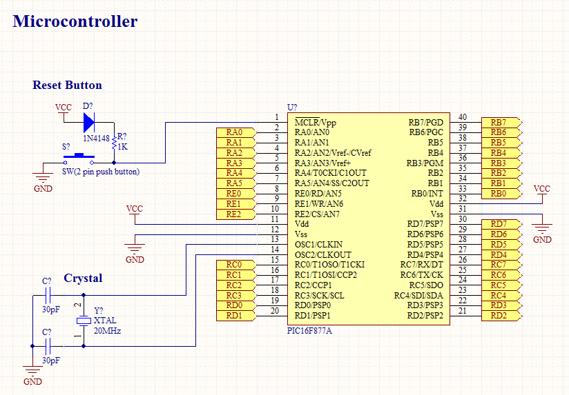
To operate a microcontroller, basic components are required to support its functionality, which is referred to as a basic circuit. The components needed are common and readily available at any electronics store. This document presents the schematic of a...
A radio remote control system utilizing DTMF (Dual-Tone Multi-Frequency) technology is presented. This circuit allows for the control of various electrical appliances through radio frequency signals. The described radio remote control system employs DTMF tones, which are generated by a...
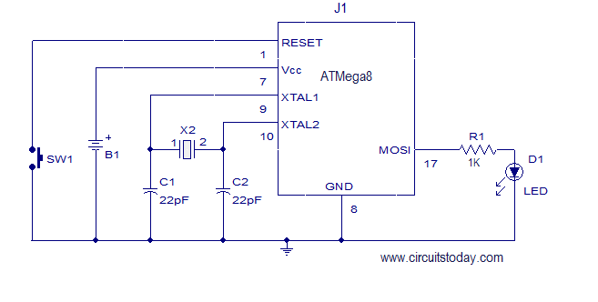
This article explains how to add a 32K external crystal/clock source to the Atmel AVR microcontroller Atmega8, including a circuit diagram and a C program. The Atmel AVR microcontroller Atmega8 is a popular choice for various embedded applications, often requiring...
This design was never completely finished, so consider it to be in the very early experimental stage. I don`t sell kits, programmed PLD`s, or provide support for this project, and I will never be published. But if you want...
The first example utilizes a standard op-amp oscillator circuit to produce a triangular waveform, which is then level-shifted and supplied to a comparator (e.g., LM339) to generate a PWM waveform. It is common for users to prefer using two...
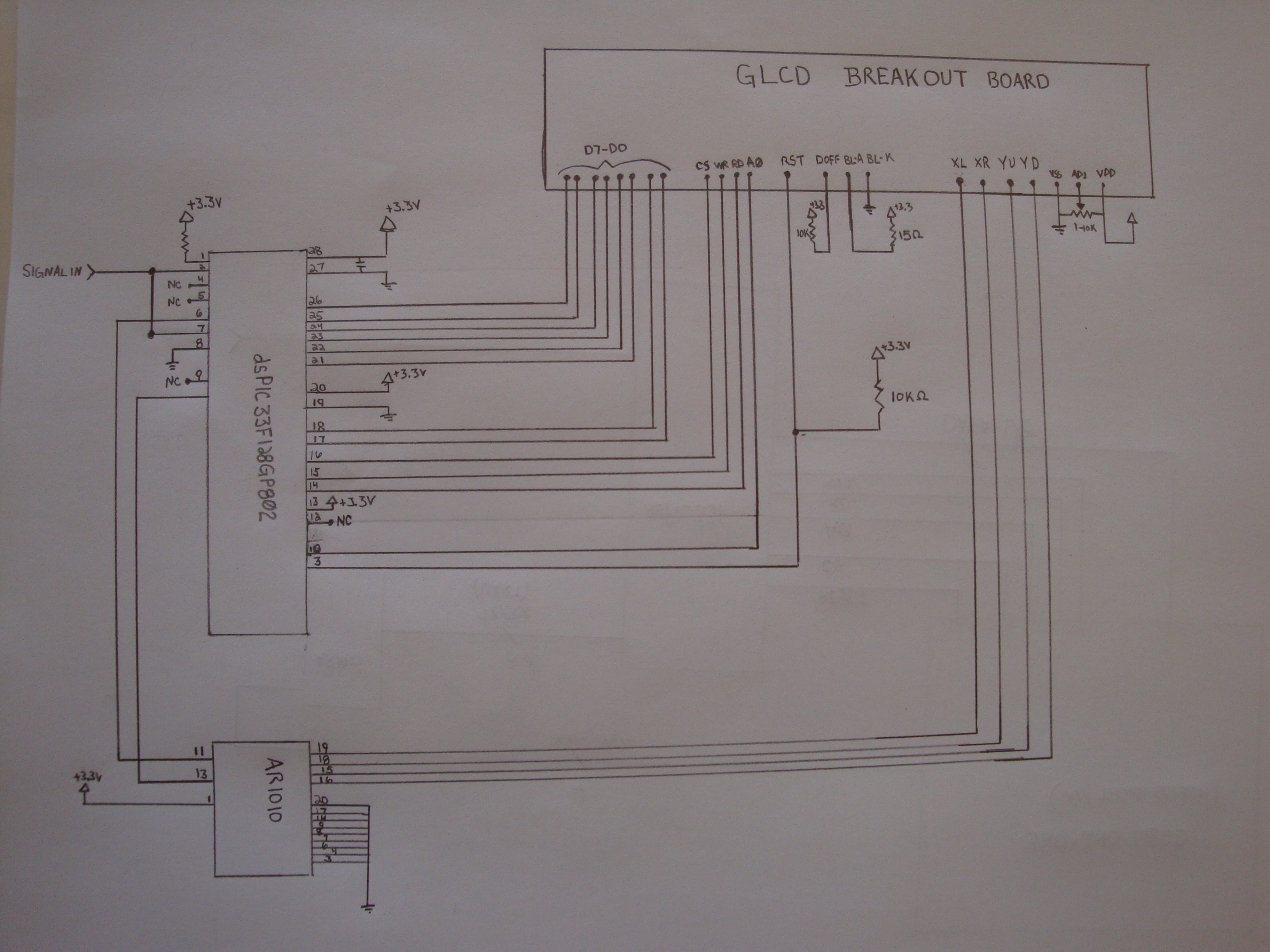
To achieve this project, the initial concept involves sampling an input using an Analog-to-Digital Converter (ADC) at consistent time intervals and subsequently displaying the waveform on a graphic LCD. Adjusting the time scale can be done by modifying the...
Warning: include(partials/cookie-banner.php): Failed to open stream: Permission denied in /var/www/html/nextgr/view-circuit.php on line 713
Warning: include(): Failed opening 'partials/cookie-banner.php' for inclusion (include_path='.:/usr/share/php') in /var/www/html/nextgr/view-circuit.php on line 713