
Fuse-Cum-Power Failure Indicator with alarm
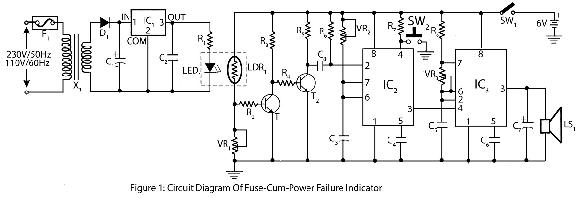
The Fuse Cum Power Failure Indicator is an essential device designed to alert users of power interruptions, thereby preventing potential damage to connected electronic equipment. The core of this circuit is the NE555 timer IC, which operates in a monostable mode to provide a time delay for the indication signal.
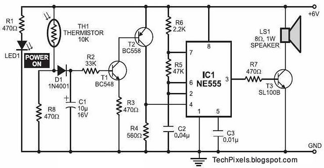
The circuit begins with a thermistor, a temperature-sensitive resistor that changes its resistance based on ambient temperature. In this application, it is used to detect the absence of power. When the power supply is interrupted, the thermistor's resistance changes, triggering the NE555 timer.
The NE555 timer is configured with a resistor-capacitor (RC) time constant that determines the duration of the output signal. When the power failure is detected, the timer activates, generating a high output signal for a predetermined period. This output can be used to drive an LED indicator, providing a visual alert to users.
The complete circuit includes additional components such as resistors, capacitors, and possibly a relay, depending on the load requirements. The parts list should detail each component's specifications, including resistance values, capacitance, and power ratings, ensuring that the circuit operates reliably under various conditions.
Overall, the Fuse Cum Power Failure Indicator is a practical solution for monitoring power supply status, safeguarding electronic devices from unexpected outages.Fuse Cum Power Failure Indicator employs thermister and timer IC NE555 circuit diagram with parts list of fuse cum power failure indicator indicate power failure. 🔗 External reference
Related Circuits

Removing R1 or R2 from the circuit allows a potential thief to break a hidden wire that connects R1 to +12 V and R2 to ground. This action activates the alarm for approximately five minutes. The circuit in question is...
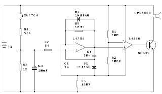
This circuit activates an alarm when its sensor comes into contact with water. It employs a 555 astable multivibrator that generates a tone of approximately 1 kHz upon water detection. The circuit consists of a 555 timer configured in astable...
When the switch is pressed, capacitor C3 charges through resistor R4 with a time constant of 0.47 seconds. Upon releasing the switch, C3 discharges more slowly through resistors R7 and R3, with a time constant of approximately 5 seconds....
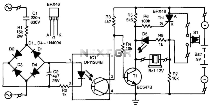
When the mains voltage is present at the input terminals, the transistor in the optocoupler is activated, T1 is off, and the silicon-controlled rectifier (SCR) Th1 is in the conducting state. As a result, both terminals of the piezoelectric...
The following circuit illustrates a fire alarm circuit diagram utilizing the NE555 integrated circuit (IC). Features include functioning as a heat sensor and incorporating a 10 kilo-ohm resistor. The fire alarm circuit based on the NE555 IC is designed to...

The modem off indicator is designed specifically for avid Internet users. The circuit for this indicator is remarkably simple, and its simplicity may lead to significant cost savings by providing a clear visual indication of whether the telephone line...