
Battery Tester/Indicator/Monitor
The battery tester circuit is designed to assess the voltage level of a battery and provide a visual indication of its status. It typically employs a voltage divider network to scale down the battery voltage to a measurable level suitable for comparison with reference voltages. The circuit often incorporates a comparator, such as an operational amplifier, which compares the scaled voltage against predefined thresholds representing normal, under-voltage, and over-voltage conditions.
When the battery voltage is within the normal range, the output of the comparator is activated, lighting an LED or activating a display to indicate that the battery is functioning correctly. If the voltage falls below the normal range, the comparator triggers a different LED or alert mechanism, indicating under-voltage, which suggests that the battery may require recharging or replacement. Conversely, if the voltage exceeds the upper threshold, another indicator will signal that the battery is over-voltage, which could indicate potential damage or malfunction.
Additional components may include resistors for setting the reference voltage levels, capacitors for filtering any noise in the signal, and possibly a microcontroller for more advanced features such as data logging or communication with other devices. The circuit can be powered by the battery being tested or an external power source, ensuring versatility in various applications. This battery tester circuit is essential for maintaining the health of battery-operated devices and ensuring optimal performance.This is a battery tester circuit.This circuit is used to indicate whether the level of a battery voltage is normal, under-voltage, or over-voltage, very.. 🔗 External reference
Related Circuits

The circuit is a battery-powered voltage regulator that outputs 12V at 1.5A. It accepts an input voltage range from 5V to 13V. The circuit utilizes the MC34063 integrated circuit, making it a straightforward design. The circuit primarily functions as a...
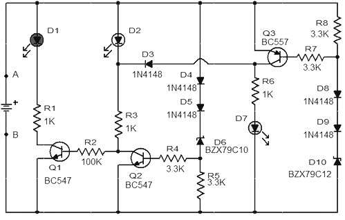
When the battery voltage is 11.5V or less, transistor Q1 is activated, and LED D1 will illuminate. When the battery voltage is between 11.5V and 13.5V, transistor Q2 is activated, causing LED D2 to light up. At a battery...
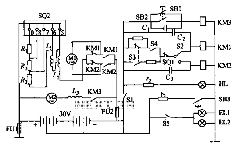
Battery forklifts are commonly used as stacking and handling tools in railway stations, docks, and warehouses. The battery shape and electrical control circuitry are depicted in the schematic. The system consists of batteries connected in series to form a...
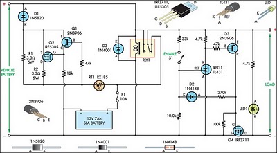
This circuit is designed to switch power to a Peltier cooler in a vehicle. Power is supplied to the load from the vehicle's battery when the ignition switch is on and from an SLA auxiliary battery when the ignition...
The operating principle of the circuit is very simple. The first LED D1 is placed in series with the resistor R2 and diode D4. An only be lit this LED indicates that the battery is ypofortismeni. For this reason,...
This circuit diagram represents an indicator designed to display a battery voltage of 12 volts. The working principle involves comparing the battery voltage with a reference voltage using the LM324 integrated circuit, which is a low-power quad operational amplifier....