
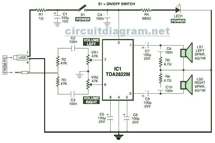
USB Powered Stereo PC Multimedia Speaker
The schematic includes components that allow the activation of an LED from a home electrical power line. To achieve this, a non-polar capacitor and a 1Kohm / 1W metal oxide resistor can be added to activate the LEDs in series. It is important to change the capacitor value from 0.47uF/250V to 0.22uF/400V for use with a 240VAC power supply.
The Arduino Uno schematic diagram is also referenced. The Arduino Uno is a microcontroller board based on the ATmega328, featuring 14 digital input/output pins (six of which can be used as PWM outputs), six analog inputs, a 16 MHz crystal oscillator, a USB connection, a power jack, and an ICSP header.
Additionally, a schematic diagram for a solar-powered mobile phone battery charger is mentioned. This circuit is designed to charge a battery from a source with a lower voltage. It is crucial not to use this circuit to charge a battery with a voltage equal to or lower than that generated by the solar panel to ensure proper operation.
The USB-powered multimedia speaker circuit provides an efficient and practical solution for audio output from computers, leveraging existing USB technology for power and audio transmission. The integration of the TDA2822M IC allows for effective amplification of audio signals, while the PCM2706 sound card enhances audio processing capabilities, enabling a straightforward connection to a computer without the need for additional software. The design's adaptability to various power sources, including USB and home electrical lines, further extends its usability in diverse applications.USB Powered, Stereo PC Multimedia Speaker Circuit Diagram. This circuit is powered by 5V DC source obtainable from the USB port of the Computer. When electrical power switch S1 is turned to on` position, 5V power supply is extended towards the circuit and power indicator red LED1 illuminates immediately. Resistor R1 is actually a current surge lim iter and capacitors C1 and C4 work as buffers. This is the circuit diagram of USB powered computer speaker, or it widely known as multimedia speakers for PCs. The circuit has single-chipbased design, low-voltage electrical power supply, compatibility with USB power from computer, simple heat-sinking, inexpensive, large flexibility and wide temperature tolerance.
At the heart of the circuit is IC TDA2822M. This IC is, . Nowadays, almost all computer systems have logic blocks for working with a USB port. A USB port, in practice, is capable of supplying more than 100 mA of continuous electric current at 5V to the peripherals which are hooked up with the bus. So a USB port could be utilized, without having any problems, for. Here the USB Sound Card circuit based on PCM2706 which dedicated for USB audio. With USB controller module inside PCM2706, there is no more additional programming to the IC. The computer system will automatically detect this circuit when connected tho the USB port. You will get stereo audio channel output from this circuit. Schematic: Components:. You can easily activate the LED from home electrical power line with this circuit diagram. You just need to add a nonpolar capacitor and a 1Kohm / 1W metal oxide resistor to activate the LEDs from home power line with serial connection.
Note: Change the capacitor value from 0. 47uf/250V to become 0. 22uF/400V for 240VAC power. Here the Arduino UNO schematic diagram (click to enlarge): About Arduino UNO: The Arduino Uno is really a microcontroller board based on the ATmega328. It has 14 digital input/output pins (of which 6 may be employed as PWM outputs), 6 analog inputs, a 16 MHz crystal oscillator, a USB connection, a power jack, an ICSP.
This is the schematic diagram of solar powered mobile phone battery charger. The circuit is designed to charge the battery from a source with a lower voltage. Do not use it to charge the battery with the same or lower voltage than the voltage which is generated by the solar panel. For proper operation of. 🔗 External reference
Related Circuits
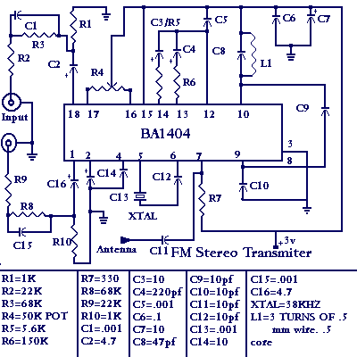
You'll find that this is a very easy project to build. It will transmit good quality sound in the FM band (88 - 108 MHz). One important item is that the IC chip operates on 3 volts DC. The...
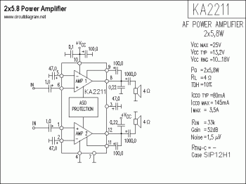
KA2211 is a dual audio power amplifier intended for consumer applications. It is designed to deliver high power with low dissipation and low noise. Additionally, it includes various protective features and is suitable for high-performance car audio applications. The KA2211...
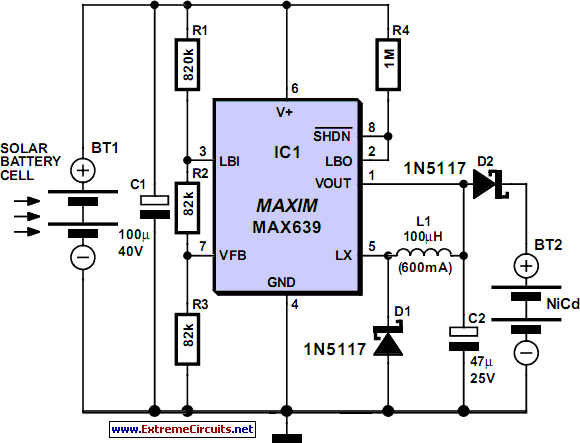
This is a simple NiCd battery charger powered by solar cells. A solar cell panel or an array of solar cells can charge a battery at more than 80% efficiency, provided the available voltage exceeds the fully charged battery...
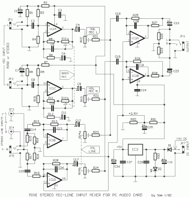
Most sound cards in computers lack stereo input for microphones, but they do have stereo inputs for high-level signals (Line). This circuit utilizes the Line input of the sound card to connect two mono microphones to the sound card's...
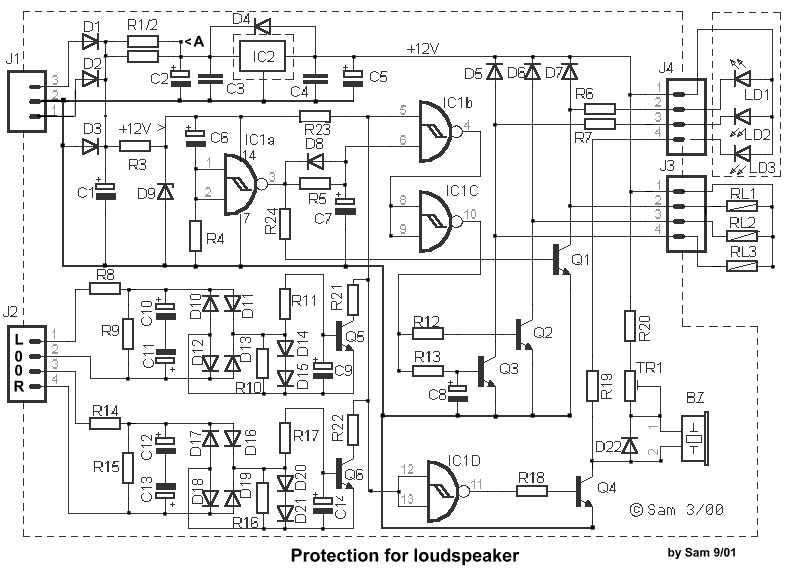
The circuit integrates several functions, including a smooth startup for the AC power line, with a one-second delay before connecting to the power supply transformers of the amplifier through relay RL1 and resistor Rx. This delay is designed to...
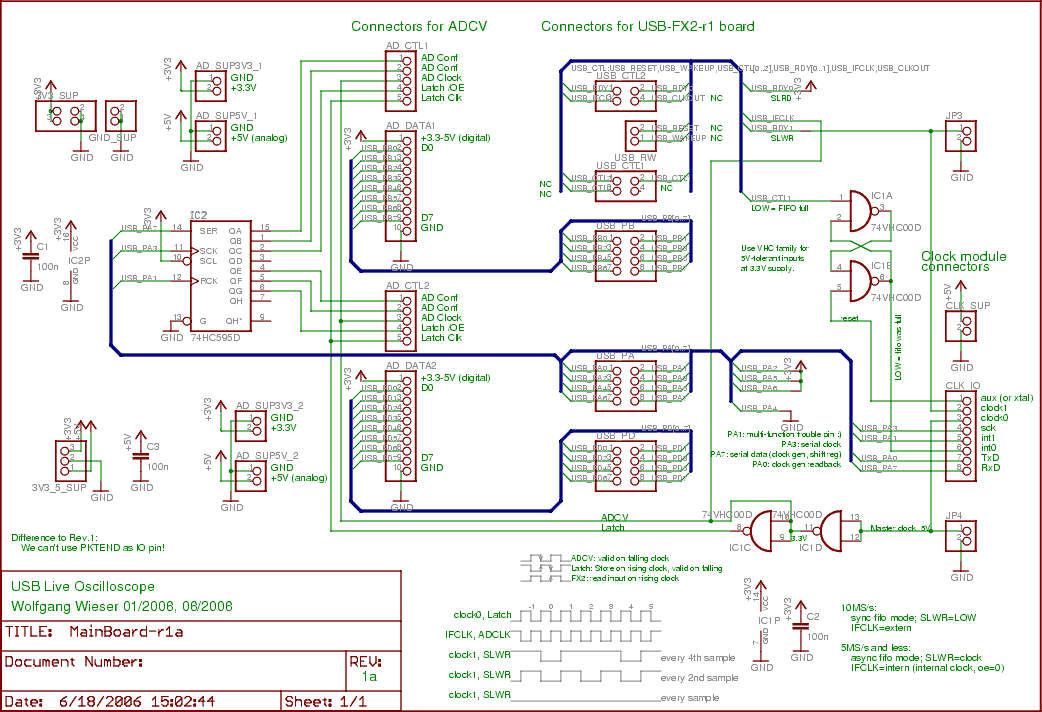
The two input boards (ADCV or digital) are connected to AD_CTL1, AD_DATA1, AD_SUP5V_1, and AD_SUP3V3_1 for the first board, with the second board using the same connections but with a suffix of 2. To transfer sampling data, the 16...