
Solar-Powered High Efficiency Battery Charger
The described NiCd battery charger circuit utilizes solar energy to efficiently charge nickel-cadmium batteries. The design incorporates a solar cell array capable of generating sufficient voltage to overcome the forward voltage drop of the diode, ensuring effective charging. The arrangement allows for a high efficiency of over 80%, which is critical for optimizing the performance of solar-powered applications.
The step-down regulator, specifically the MAX639, is a key component in this circuit. Operating in "Elektor mode," it regulates the input voltage rather than the output voltage, which is atypical for most regulators. This approach allows for dynamic adjustment of the charge current flow, ensuring that the output voltage from the solar cells remains at an optimal level for maximum power transfer to the batteries.
The circuit's design features a potential divider configuration that plays a crucial role in managing the charging process. The R2/R3 divider disables the internal regulation loop, allowing for a more responsive charging strategy. In contrast, the R1/R2+R3 divider enables the low battery input to detect when the solar array output voltage drops, triggering the low battery output to deactivate the chip when necessary. This intelligent management system ensures that the batteries are charged efficiently while protecting them from over-discharge.
Current limiting functionality within the MAX639 is designed to prevent excessive current draw, with a maximum output current of 200 mA. This is particularly important when charging multiple NiCd cells in series, as it helps maintain the integrity and longevity of the battery pack. The internal switch of the regulator, with its low resistance, minimizes power loss during operation, contributing to the overall efficiency of the charger.
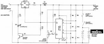
In summary, this solar-powered NiCd battery charger represents a sophisticated design that maximizes the efficiency of solar energy utilization. By employing advanced regulation techniques and intelligent battery management, the circuit is capable of delivering reliable power to battery packs in various applications. The inclusion of a suppressor choke further enhances the circuit's performance by reducing potential noise and improving stability during operation.This is a simple NiCd battery charger powered by solar cells. A solar cell panel or an array of solar cells can charge a battery at more than 80 % efficiency provided the available voltage exceeds the fully charged` battery voltage by the drop across one diode, which is simply inserted between the solar cell array and the battery. Adding a step-do wn regulator enables a solar cell array to charge battery packs with various terminal voltages at optimum rates and with efficiencies approaching those of the regulator itself. However, the IC must then operate in an unorthodox fashion (a. k. a. Elektor mode`) regulating the flow of charge current in such a way that the solar array output voltage remains near the level required for peak power transfer.
Here, the MAX639 regulates its input voltage instead of its output voltage as is more customary (but less interesting). The input voltage is supplied by twelve amorphous solar cells with a minimum surface area of 100 cm2.
Returning to the circuit, potential divider R2/R3 disables the internal regulating loop by holding the V-FB (voltage feedback) terminal low, while divider R1/R2+R3 enables LBI (low battery input) to sense a decrease in the solar array output voltage. The resulting deviation from the solar cells` peak output power causes LBO (low battery output) to pull SHDN (shutdown) low and consequently disable the chip.
LBI then senses a rising input voltage, LBO goes high and the pulsating control maintains maximum power transfer to the NiCd cells. Current limiting inside the MAX639 creates a ceiling` of 200 mA for I out. Up to five NiCd cells may be connected in series to the charger output. When on` the regulator chip passes current from pin 6 to pin 5 through an internal switch representing a resistance of less than 1 ohm.
Benefiting from the regulator`s low quiescent current (10 microamps typical) and high efficiency (85 %), the circuit can deliver four times more power than the single-diode configuration usually found in simple solar chargers. Coil L1 is a 100- µH suppressor choke rated for 600 mA. 🔗 External reference
Related Circuits
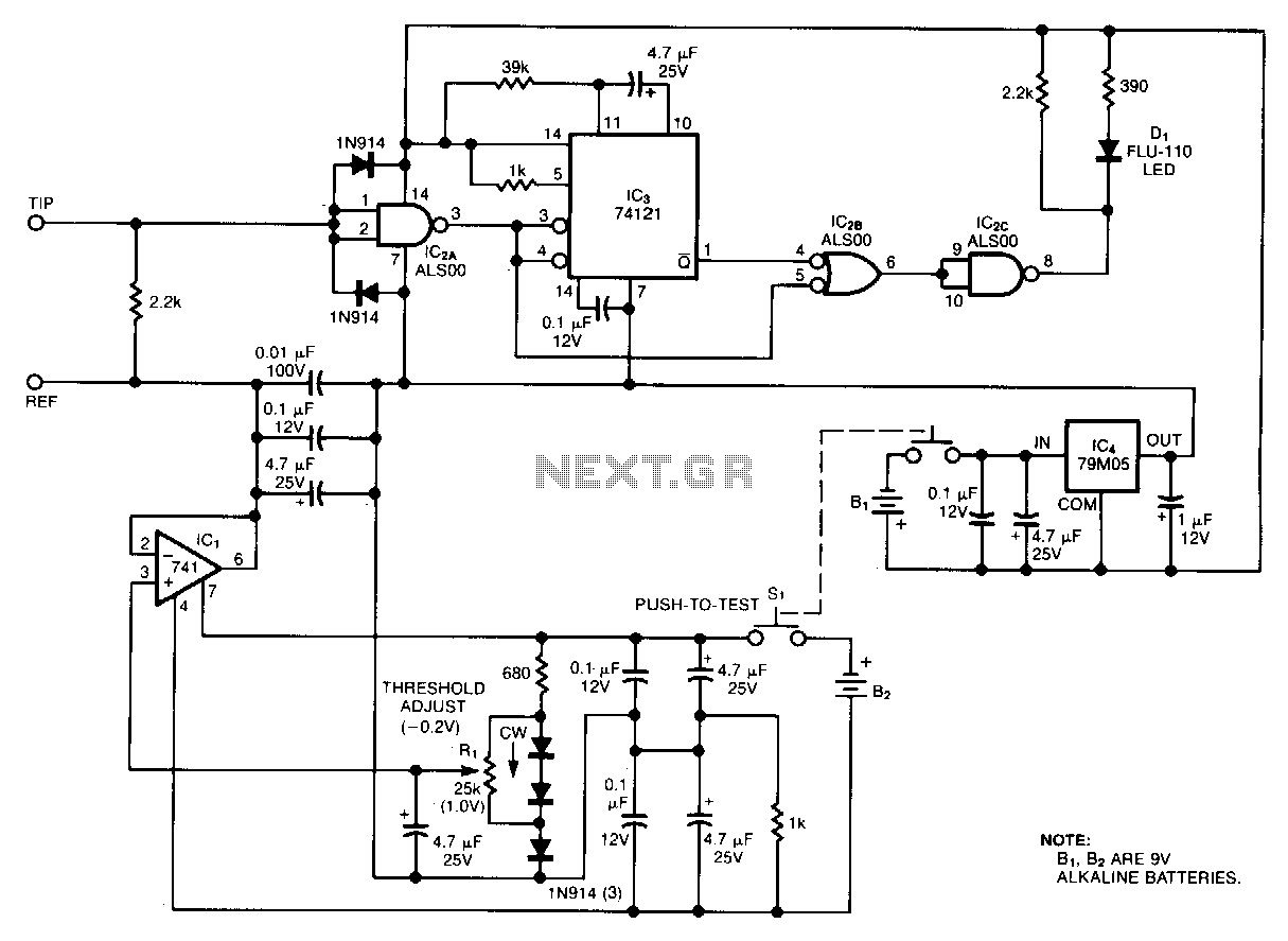
Oscilloscope measurements of ground noise can be unreliable because noise can enter your circuit via the scope's three-pronged power plug. This issue can be mitigated by utilizing the ground-noise tester described. The circuit operates on two 9-V batteries and...
This discussion assists in selecting the most appropriate microprocessor supervisor integrated circuit (IC) for specific applications and provides solutions for various common supervisory issues encountered with microprocessors. Microprocessor supervisor ICs are critical components in ensuring the reliable operation of microprocessor-based...
This circuit is designed to flash a white LED using a supply voltage ranging from 2V to 6V, resulting in a very bright flash. The circuit operates at approximately 2mA, allowing the use of old batteries. When powered at...
This document outlines a battery monitoring circuit designed to measure the voltage of 12V lead-acid batteries, such as those used in automobiles. The circuit utilizes the LM3914 integrated circuit (IC) along with several external components, including a series of...
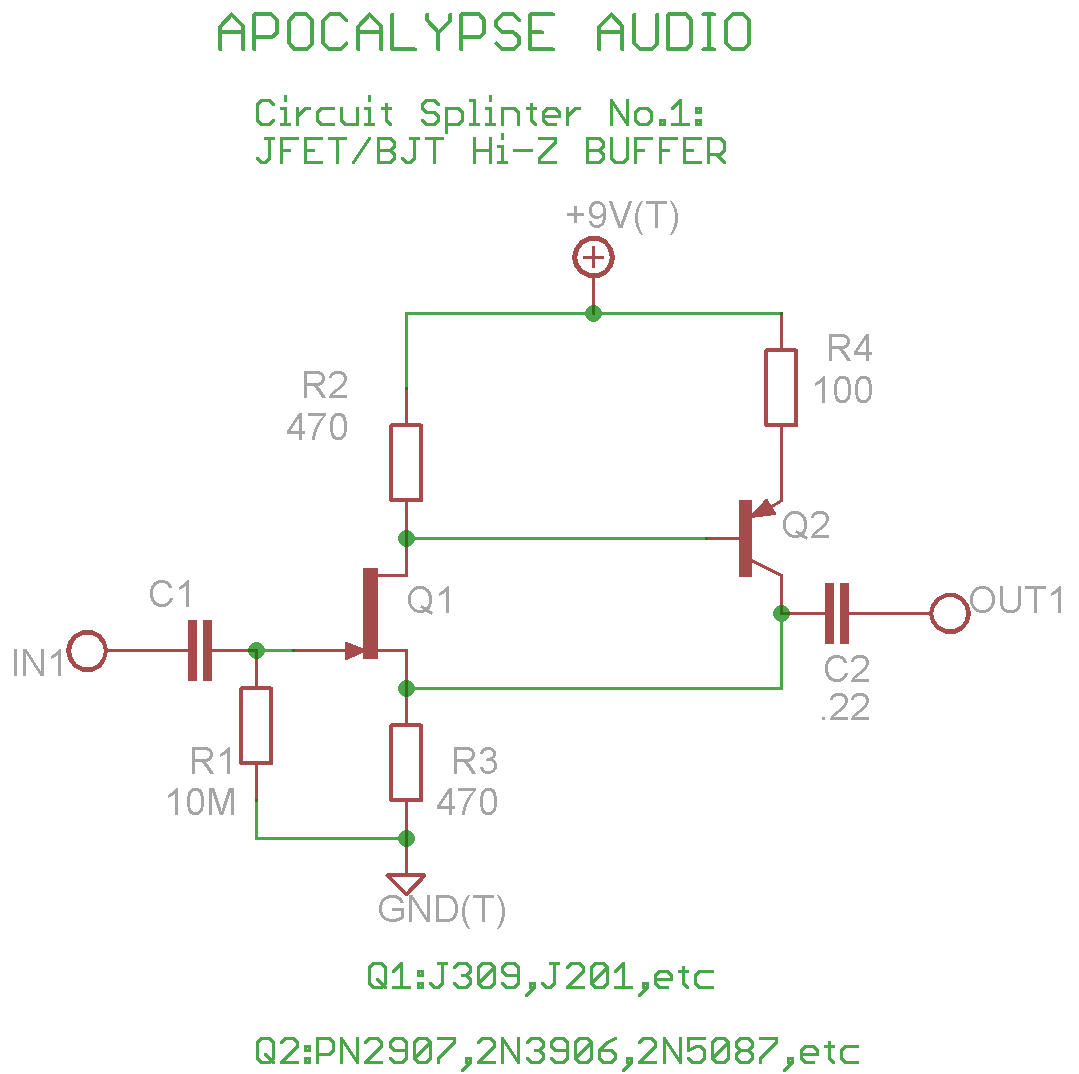
This is a common circuit often found in various resources, yet it appears to be less prevalent in stompbox applications. The circuit utilizes an NPN JFET DC coupled with a PNP BJT. The FET provides a significantly higher input...
This circuit illustrates a Lithium Battery Charger circuit diagram. Charging is achieved using a constant current of 60 mA for AA cells until a cutoff voltage of 2.4V per cell is reached, at which point the charging process must...