
Use Analog Techniques To Measure Capacitance In Capacitive Sensors

For example, a capacitive relative humidity (RH) sensor employs a dielectric material that absorbs water vapor from the surrounding environment. As the dielectric absorbs moisture, its electrical capacitance increases due to a rise in the dielectric constant, serving as a direct indicator of relative humidity. The dielectric constant is also sensitive to temperature changes, necessitating simultaneous measurements of capacitance and temperature for accurate humidity calculations. Humidity sensors typically exhibit small capacitance changes across their output range, with a change of 40 to 50 pF observed from 0% to 100% RH, where the capacitance at 0% RH (C0RH) ranges from 100 to 200 pF. A typical sensor may provide 3% absolute accuracy (with 1% repeatability), translating to a resolution requirement of 1.5 pF.
Capacitive sensors can also be used for displacement measurements. In their simplest configuration, these sensors consist of precision metal plates positioned closely together, maintaining an electric field between them. The output capacitance, which is typically small (in the 10-pF range), varies significantly based on the sensor's geometry. The common method for measuring capacitive sensors involves using an analog timer circuit to generate a frequency inversely proportional to capacitance, allowing a microcontroller to count pulses over a set period to determine the frequency. This approach eliminates the need for an analog-to-digital converter (ADC) or comparator within the microcontroller. The fundamental equation linking the measured capacitance (C) and frequency (F) is straightforward.
Digitizing the output from a capacitive sensor often requires generating a frequency inversely related to capacitance and counting pulses over a specified duration to ascertain the frequency. Astable timers, such as the classic 555 timer, function by charging and discharging a capacitor, with the capacitor voltage triggering these cycles as it crosses predefined lower and upper thresholds. Although specifications may indicate operation above 1 MHz, typical CMOS 555 timers usually operate in the 5 to 10 kHz range for optimal accuracy.
The schematic illustrates both passive and active compensation methods, with a capacitor (CX) of 4 pF. In an active shielding scenario, a capacitor located remotely connects to the timer through 12 inches of RG316 shielded cable (29.4 pF/ft). The resulting plots display measurements under conditions of no compensation, passive compensation, and active shielding. A table outlines basic limitations of these circuits, indicating that a few picofarads of input capacitance exist on the trigger (TH) and threshold (TR) pins. As these pins connect to the capacitor being measured, this parasitic capacitance, combined with stray capacitance, erroneously contributes to the measured capacitor value. For capacitance measurements exceeding 100 pF, these factors can significantly impact accuracy.Capacitive sensors are found in a wide range of equipment, from consumer electronics to industrial/process control. Touch buttons are increasingly found in lamps and dimmers. Motion detectors can detect miniscule changes in deflection. Hygrometers indicate humidity changes. Pressure sensors and accelerometers are moving toward capacitive sensing. And, capacitive displacement sensors are even found in disk drives. These sensors produce an output: capacitance. Measuring this capacitance is an inherently analog problem that can be very tricky. Often, these sensors provide the most trouble for engineers to interface to microcontrollers. While some microcontrollers offer built-in simple routines for capacitive touch buttons, their measurements are relatively crude and designed for measuring a change in capacitance ”useful for detecting a finger placed on a touch sensor, but not for industrial and displacement sensing requiring absolute accuracy. As a specific example of a capacitive sensor, consider a capacitive relative humidity (RH) sensor. In this type of sensor, the dielectric material is designed to absorb water vapor from the external environment when exposed.
The electrical capacitance increases as the dielectric absorbs water, since the dielectric coefficient increases with increased moisture ”a direct indication of the relative humidity. The net dielectric coefficient is also sensitive to temperature variations, so the humidity calculation involves both a measurement of capacitance and temperature.
Humidity sensors exhibit a relatively small change in capacitance over their output range. A capacitance change of 40 to 50 pF over 0% to 100% RH with a 0% RH capacitance (C0RH) of 100 to 200 pF is not uncommon. A typical sensor offering 3% absolute accuracy (with 1% repeatability) corresponds to a resolution requirement of 1.
5 pF. Some capacitive sensors measure displacement. In their simplest form, these sensors are constructed with precision metal plates in close proximity, and an electric field is maintained between them. The resulting output capacitance (usually small, in the 10-pF range) depends widely on the geometry of these sensors.
The most common approach to measuring capacitive sensors is simply to use an analog timer circuit to generate a frequency that is inversely proportional to capacitance and then utilize a microcontroller to count pulses within a given period to calculate the frequency ( Fig. 1 ). Thus, there is no requirement for an analog-to-digital converter (ADC) or comparator in the microcontroller.
The basic equation relating the measured capacitor C and frequency F is: 1. Digitizing the value of a capacitive censor often involves generating a frequency that is inversely proportional to the capacitance and counting pulses over a fixed period to determine the frequency. Astable timers, such as the classic 555, operate by charging and discharging a capacitor. The capacitor voltage triggers the charge and discharge cycles as it transitions across a lower and upper threshold.
Despite specifications touting higher than 1-MHz operation, typical CMOS 555s like to operate in the 5- to 10-kHz range for best accuracy ( Fig. 2 ). 2. The schematic (a) illustrates passive and active compensation methods: CX = 4 pF. For an active shield, a remotely located capacitor is connected to the timer across 12 in. of RG316 shielded cable (29. 4 pF/ft). The plots show measured results for no compensation, passive compensation, and active shield conditions.
The table shows some basic limitations in these circuits. Error A, the first, shows that a few picofarads of input capacitance exist on the TH and TR pins. Since this is the connection point for the capacitor measured, this parasitic capacitance (along with the stray capacitance shown in row F in the table) adds erroneously to the measured capacitor value. For capacitance measurements above 100 pF, this can be 🔗 External reference
Related Circuits
The all-analog circuit presented controls the rate at which a miniature turbojet engine can be throttled. Increasing or decreasing the throttle too quickly on a miniature turbojet engine, or any jet engine, can lead to quick failure in flight,...
The VU meter is categorized into two types: those that use needle instruments and those that employ LED columns. A VU meter sound level meter is essential for both tube amplifiers and integrated amplifiers. Currently, there are numerous integrated...
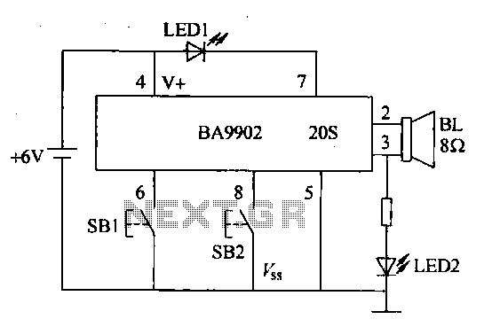
The voice recorder's entry information can be stored for 100 years, repeated 100,000 times, with low power consumption. It requires a 5-6V DC power supply and has a recording current of 2 mA. The voice recorder circuit is designed to...
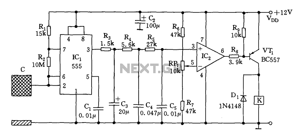
The switch circuit consists of a capacitive oscillator, an integration network, and a comparator circuit that controls a relay. When a body comes close to the induction plate, the inductive capacitance to ground increases, causing the 555 astable multivibrator...
This example implements a clock using 36 lines of Perl code. It displays the time and date, with a small icon called "heartbeat" in the upper right corner. The "heartbeat" icon, added by the LCDd server, blinks intermittently to...
This post discusses the interfacing and operation of Analog-to-Digital Converters (ADCs). An ADC is a device that converts the analog signals from transducers into digital signals, enabling computers to process the data. ADCs are essential for obtaining meaningful results...