
Useless Electronic Circuits
The circuit described is a simple yet engaging logic puzzle that can be constructed using basic electronic components. It typically consists of a microcontroller or a logic gate configuration, several push buttons, LEDs for visual feedback, and a buzzer for incorrect attempts.
The microcontroller serves as the central processing unit, managing the input from the buttons and controlling the output to the LEDs and buzzer. The buttons are connected to the microcontroller's input pins, and each button press is registered through a digital input. The logic for the correct sequence is programmed into the microcontroller, allowing it to compare the order of button presses against a predetermined sequence stored in its memory.
When the user presses a button, the microcontroller checks if the button corresponds to the next expected input in the sequence. If the input is correct, the microcontroller activates the next LED in the series, providing visual feedback that the user is on the right track. If an incorrect button is pressed, the microcontroller triggers the buzzer, indicating a mistake has been made.
To enhance the circuit's interactivity, the buttons can be rewired to create new sequences, allowing users to modify the puzzle without needing advanced technical skills. This reconfiguration can be achieved by simply changing the connections on a breadboard or using jumper wires, making the circuit accessible for individuals of all skill levels.
The overall design encourages creativity and problem-solving, as users can experiment with different button sequences and challenge themselves or others to complete the puzzle. This circuit not only serves as an entertaining game but also provides a hands-on learning experience in electronics, logic design, and programming.Here I will post some cool looking, challenging yet extremely fun electronic circuits you can build. I studied Electronics most of my life, since I was in middle school electronics have been my passion and have been creating some circuits since then. Most of the time when you get informa tion about electronics it is to make some tool you can use to do some other task, it made sense, to use knowledge to facilitate a task. But after making countless semi-useful electronic circuits I became a little bored with them, the thrill of creating them faded after it was done.
So I decided to start making electronic circuits that I can have fun with after i finish them, like puzzles, small games, a little gadget or some other stuff I could share with friends and family. In that process I noticed many people actually like useless electronics, they found them fun and amusing, so I decided to share my cute little circuits online, so that other electronics enthusiast and their friends may benefit from them.
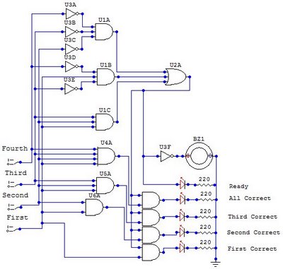
The first circuit is a little puzzle I created. The purpose is to press a series of buttons in the correct order, if you press the wrong one you`ll get the "loser-buzzer", kind of like what happens in that know board game that I can`t remember the name, where you play doctor. The exact rules are up to you, there is a little catch to use the circuit, you have to rewire the buttons to make a new combination, but that is easy and doesn`t even require technical knowledge.
The puzzle itself is a logic circuit, designed so that only the correct order of the buttons will turn on the indicator leds, any other will trigger the loser-buzzer. 🔗 External reference
Related Circuits
555 timer circuits LM555 - Astable Oscillator Calculator, Capacitor Calculator, Basic Circuits for the LM555 Timer, Triggering and Timing Helpers for Monostable Timers, Controlling Circuits for LM555 Timers, Advanced Circuits for the LM555 Timer, LM556 Timers with Complementary or...
The circuit below illustrates powering one or two LEDs from the 120-volt AC line using a capacitor to drop the voltage and a small resistor to limit the inrush current. Since the capacitor must pass current in both directions,...
The circuit presented is a standard Colpitts oscillator, commonly utilized in many amateur radio homebrew transmitters. This specific circuit is designed to operate effectively within a frequency range of 1500 kHz to 8000 kHz. To accommodate lower frequencies, it...

A simple 16-volt switching power supply circuit can be constructed using the provided diagram, which is based on the MAX668 constant-frequency, pulse-width modulating (PWM), current-mode DC-DC controller. This integrated circuit is designed for a wide range of DC-DC conversion...
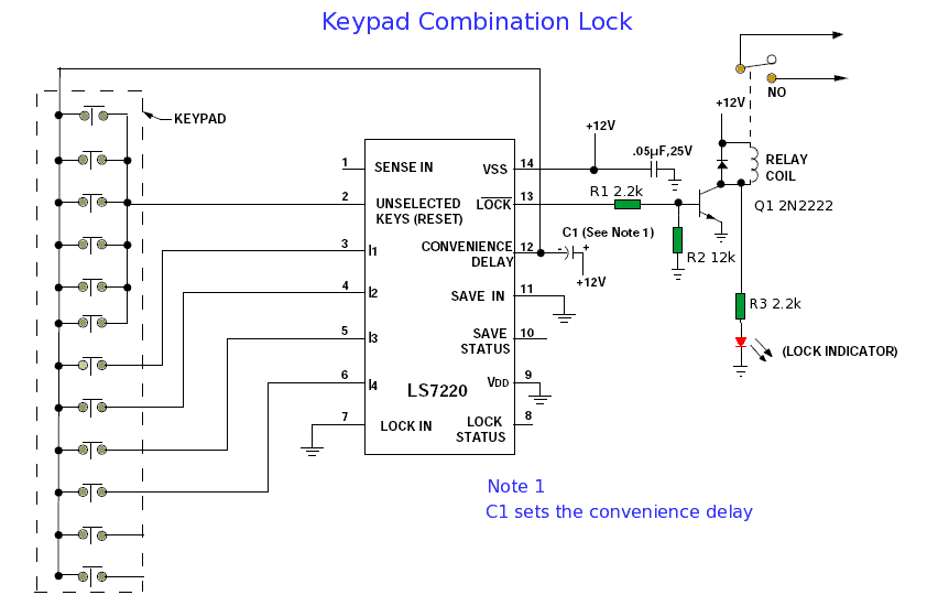
When connected to a ten-digit keypad, the circuit can identify one four-digit combination from a total of 5040 possible codes. Upon entering the correct four-digit sequence from the keypad, the LOCK feature activates while the Lock Status deactivates. The...
The circuit employs two Light Dependent Resistors (LDRs) arranged in series with a separation of approximately half a meter. This configuration allows each LDR to detect the presence of a person entering or exiting the room. The processed outputs...