
Electronic Keypad Combination Lock
The described circuit utilizes the LS7220 integrated circuit, which is designed to manage input from a keypad for security applications. The LS7220 functions as a digital lock controller, processing the input signals from the keypad to determine if the entered combination matches the pre-set combination.
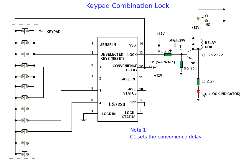
The ten-digit keypad consists of individual switches for each digit, ensuring that each key press is registered distinctly. The connection of the keys to the LS7220 is critical for accurate detection; thus, proper wiring must be maintained. Pins 3, 4, 5, and 6 are specifically allocated for the four digits of the lock combination, while pin 2 serves as a reset line, allowing the user to clear the current combination if needed.
The return key, connected to pin 12, acts as a confirmation input, signaling the LS7220 to process the entered combination. This design ensures that the circuit can effectively manage user inputs and provide feedback through the LOCK and Lock Status indicators.
In applications where multiple key presses may occur, the circuit's design must accommodate debouncing techniques to ensure that each key press is registered accurately without false triggering. Additionally, the use of pull-up or pull-down resistors may be necessary to stabilize the input signals from the keypad.
For enhanced security, it may be beneficial to include features such as lockout mechanisms after a certain number of incorrect attempts, or the integration of additional security measures like timers or alarms. The simplicity and effectiveness of the LS7220-based lock circuit make it suitable for various applications, from simple door locks to more complex security systems.When wired to a ten-digit keypad, the circuit will recognize one 4 digit combination out of a possible 5040 codes. When the programmed four-digit combination is entered from the keypad, in proper sequence, LOCK turns on and Lock Status turns off.
The lock combination is set by pins 3, 4, 5 and 6 on the LS7220. These correspond to the digits on the k eypad. So if for example you wanted to set a combination of 8462, wire key 8 to pin3, key 4 to input 4, key 6 to input 5 and key 2 of the keypad to input 6. Any unused keys are wired to pin 2. An input on pin 2 resets the lock combination. The keypad must have individual connections for each key and a common return key. The return key is wired to pin 12 of the LS7220. The alternative is to wire a group of switches in parallel. 🔗 External reference
Related Circuits
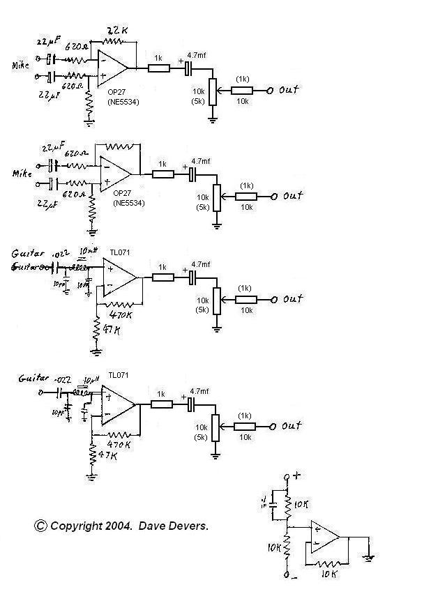
The mixer is extremely useful for direct input (DI) of guitars and basses into soundcards or other mixers, allowing for the utilization of channels on mixers that lack microphone inputs. It is particularly beneficial for one or two guitarists...
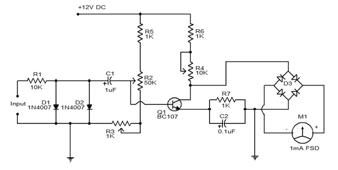
A simple tachometer schematic is presented. It utilizes a frequency converter circuit that transforms the input signal into a proportional current, which is then measured by a pointer device. The deflection of the milliammeter is proportional to the frequency...
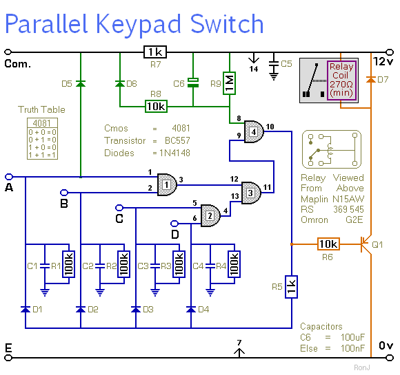
This is a universal four-digit keypad-operated switch with a unique feature. Instead of entering the security code one digit at a time, all four keypad buttons must be pressed simultaneously. This means the four numbers must be entered in...
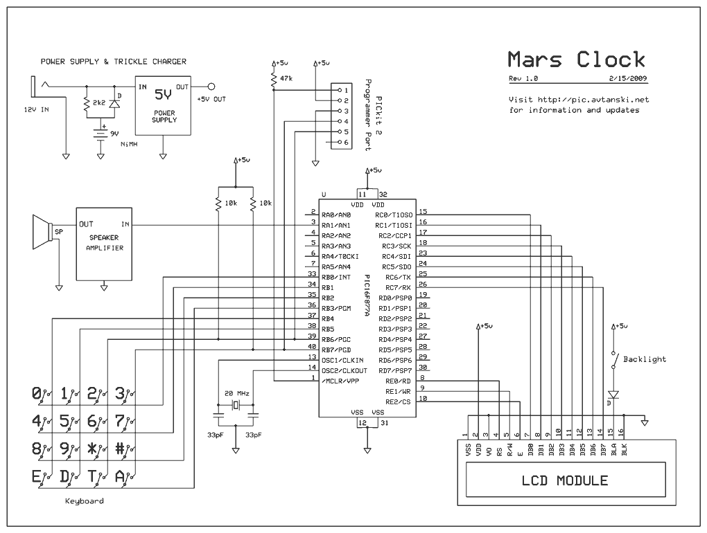
It has 16 timers that can be independently paused and restarted, and can run forward or backward. There are 16 alarms with configurable sounds and actions. Timers can show Earth, Mars, Jupiter, etc. times at the same time. How...

The origin of the idea began after a night out in March 2009. After enjoying some post-work drinks, a taxi ride home led to a situation where the driver requested smaller change than the 50 euro note being offered. The...
This is a new design for a universal gear indicator that can be fitted to any motorcycle as an aftermarket accessory. Its main advantage is that its operation depends entirely on the gear shift lever movement, instead of connecting...
Warning: include(partials/cookie-banner.php): Failed to open stream: Permission denied in /var/www/html/nextgr/view-circuit.php on line 713
Warning: include(): Failed opening 'partials/cookie-banner.php' for inclusion (include_path='.:/usr/share/php') in /var/www/html/nextgr/view-circuit.php on line 713