
Simplest atmega8 programmer Using LPT Port
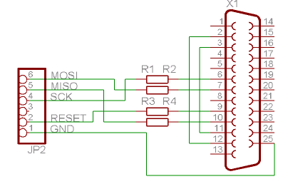
The Atmega 128 microcontroller is a versatile component within the AVR family, known for its in-system programming capabilities that facilitate firmware updates without the need for physical removal from the circuit. To establish a direct programming interface with the LPT port, a basic understanding of the required connections is essential. The key pins involved include Ground (GND), Serial Clock (SCK), Master In Slave Out (MISO), Master Out Slave In (MOSI), and Reset (RESET).
In a typical setup, the GND pin of the Atmega 128 should be connected to the GND of the LPT port to ensure a common reference voltage. The SCK pin is responsible for synchronizing the data transfer, while the MISO and MOSI pins handle the data exchange between the microcontroller and the programming software. The RESET pin is crucial for initiating the programming mode of the Atmega 128.
While the circuit can function without the protective resistors, it is advisable to include 220Ω resistors in series with the SCK, MISO, and MOSI lines. This precautionary measure mitigates the risk of overcurrent conditions that could damage the LPT port or the microcontroller itself. The resistors act as a buffer, limiting the current flowing into the pins during programming operations.
For power supply, a stable 5V (Vcc) is required to operate the Atmega 128. This voltage must be supplied from a reliable source to ensure that the microcontroller functions correctly during the programming process. The PonyProg software, which is commonly used for programming AVR microcontrollers, requires specific settings to be configured for successful communication with the Atmega 128. Ensuring that these settings are accurate is critical for the programming process to proceed without errors.
In summary, programming the Atmega 128 directly through the LPT port is a feasible approach that can be executed with minimal external components, provided that the necessary connections are made carefully, and protective measures are observed. This method allows for efficient updates to the microcontroller's firmware while maintaining the integrity of the programming interface.Atmega 128 is like other AVR microcontrollers. They are ISP is in-system programmable. Earlier I wrote an article about AVR ISP programmer where 74HC244 buffer is used. Using buffer is safer for your AVR. But what if you need 128 atmega programmer without any parts, then you can connect your microcontroller directly to LPT port or use protecti on resistors (220R) just in case. of course circuit works without resistors, but you put your LPT port at risk. Just connect GND, SCK, MISO, MOSI and RESET to adequate LPT pins and you can program atmega`s flash memory without removing it from socket. Programming software can be PonyProg. you also need power supply 5v Vcc For IC. if you Using PonyProg make sure the setting like this. 🔗 External reference
Related Circuits
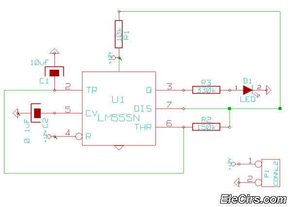
This is a very simple 555 timer circuit that serves as a straightforward theft deterrent, which may be just as effective. The idea is to have a flashing red LED indicate that your car is protected. This device can...
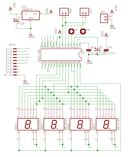
The MAX1496 is an analog-to-digital converter (ADC) that incorporates LED drivers, allowing for the construction of a 3 1/2 digit voltmeter using a minimal number of components. This device features both external and internal voltage reference options, along with...

This receiver is designed around the widely used ZN414 integrated circuit, which covers the medium wave band from approximately 550 to 1600 KHz. The coil and tuning capacitor can be salvaged from an old medium wave radio to expedite...
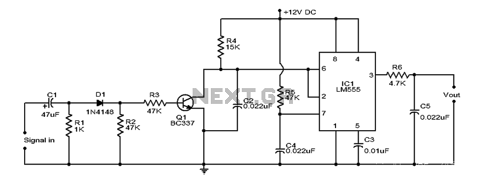
This document provides an overview of a simple circuit diagram for frequency (F and V) voltage conversion. It describes a digital frequency meter circuit primarily based on the LM555 timer IC, which is commonly used in various applications, including...
This circuit was designed to control a 32 channel Christmas light show from the PC serial port. Originally designed with TTL logic, it has been simplified using CMOS circuits to reduce component count. It is a fairly simple, reliable...
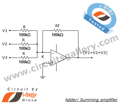
A summing amplifier, also known as an adder, is utilized to combine two or more signal voltages. This voltage adder circuit is straightforward and allows for the addition of multiple signals. It has a wide range of applications in...