
Melody Generator Circuit using UM66

The UM66 melody generator circuit is designed to produce musical tones for various applications, leveraging its built-in ROM to store melodies. The circuit's low power consumption makes it suitable for battery-operated devices. The IC requires a 3V power supply, which can be stabilized using a zener diode to ensure consistent performance.
In the schematic, the output from pin 1 of the UM66 is connected to a push-pull amplifier configuration. This setup is essential for driving low-impedance speakers, as it allows for increased power output and improved sound quality. Transistors Q1 and Q2 serve as the primary components in the push-pull stage, providing the necessary current to the speaker while minimizing distortion.
To further enhance the audio output and reduce unwanted noise, an additional amplifier stage can be included before the push-pull configuration. This pre-amplifier can filter out noise and boost the signal level, ensuring that the sound produced is clear and loud.
The UM66's compact design, similar to that of a BC547 transistor, allows for easy integration into various electronic projects. Its simplicity and effectiveness make it an excellent choice for hobbyists and engineers looking to incorporate sound generation into their designs. The overall circuit is suitable for educational purposes, as well as practical applications in consumer electronics.This circuit is a circuit diagram generator melody. This circuit controlled by the IC UM66. The UM66 CMOS IC designed for use in the call bell, telephone, and toys. Has a built in ROM that is programmed to play music. The device has a very low power for consumption. Thanks melody technology. The CMOS will be available in pin3 of UM66 and here is r einforced by using transistors Q1 and Q2 to drive the speaker. UM66 is a fun music generator IC that worked at 3V supply voltage. The following is a schematic drawing: 3V supply is required given through zener regulator. the out put is taken from pin No1 and given to the push pull amplifier to drive low impedance speakers lowd. An amplifier before pushpull amplifier can be used for noise and improve decrese out put. UM66 is a 3-pin IC Pakage just looks like a transistor BC 547. 🔗 External reference
Related Circuits
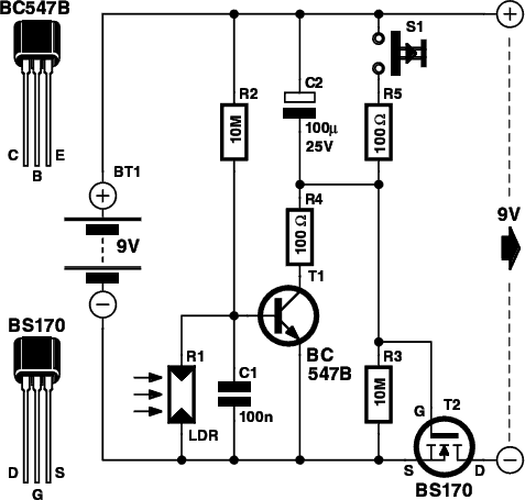
This is a small electronic switch that connects a battery to the equipment for a certain amount of time when a push-button is momentarily pressed. The ambient light level has also been considered; when it is dark, the display...
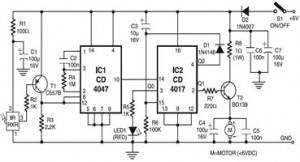
The following circuit illustrates an Infrared Toy Car Motor Controller. This circuit is based on the 4047 and 4017 integrated circuits (ICs). Features include a 16V capacitor, a 100k resistor, and the use of dual ICs. Components involved are...
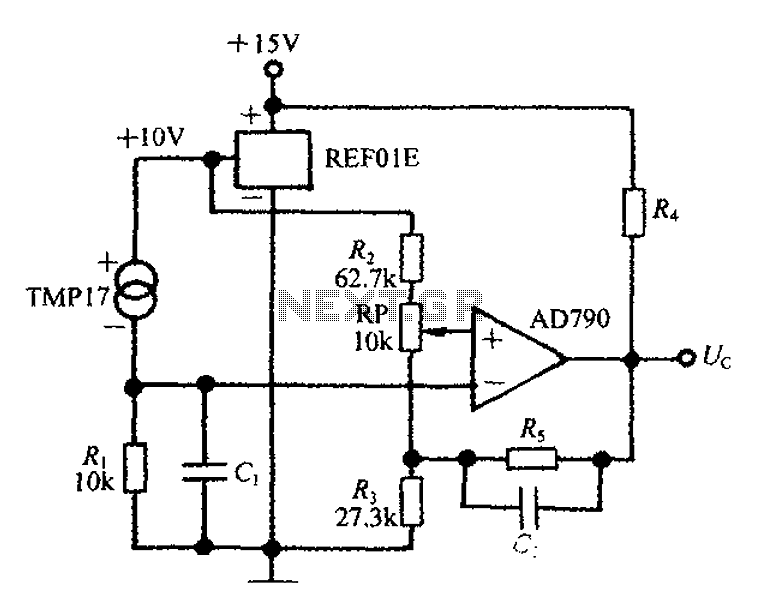
An adjustable thermostat controller circuit is widely used in everyday applications, such as for maintaining a constant temperature in soldering irons. The circuit utilizes the TMP17 sensor along with the REF01E voltage reference to ensure a stable 10V supply...
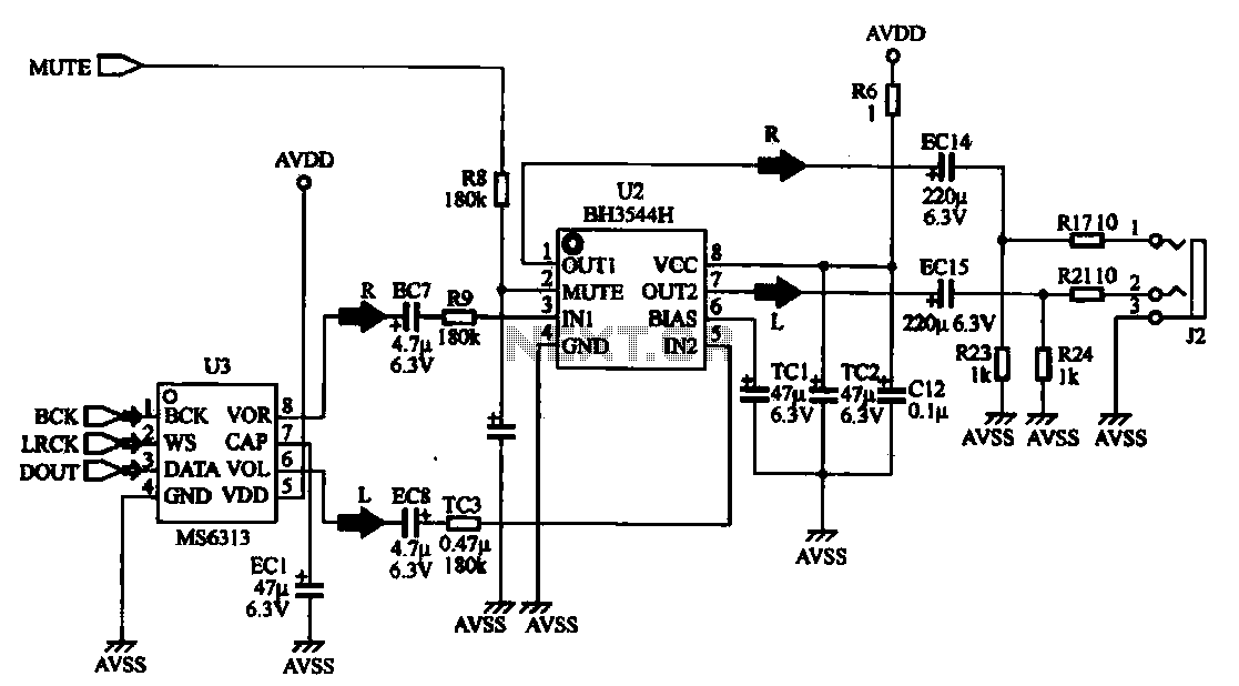
The MP4 audio circuitry consists of audio D/A converters and an audio amplifier combination circuit. This design features a straightforward circuit layout, making it suitable for integration into compact MP4 digital devices. The MP4 audio circuitry is designed to efficiently...
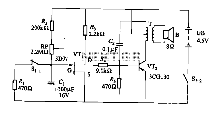
The darkroom circuit is designed for one-time exposure and emits an audible signal when the developing time is reached. This circuit can be utilized for photofinishing large timers and other applications. It comprises components such as FET VTi, resistors,...
This circuit is a motion detection sensor that utilizes a light source and detector as an infrared motion detector. The motion sensor employs an infrared LED and a phototransistor. Since it relies on light, the sensor's sensitivity can be...