
Using the joystick port as general purpose input
The joystick button inputs serve a versatile role in electronic designs, allowing for the integration of various types of input mechanisms. These inputs can be configured to function as general-purpose buttons or switches, making them suitable for a wide range of applications, from gaming controllers to industrial control panels.
The inputs can accept signals from logic level sources, which means they are compatible with digital circuits operating at standard voltage levels, typically 3.3V or 5V. Additionally, they can interface with open collector or open drain outputs, which are common in digital logic circuits. This feature allows for the connection of multiple devices to a single input line, enabling more complex control schemes without the need for additional components.
When connecting mechanical contacts such as switches, microswitches, or pushbuttons, it is critical to note that the joystick port lacks inherent hardware debouncing capabilities. Mechanical switches can produce noisy signals when toggled, leading to multiple transitions being detected instead of a single clean signal. To mitigate this issue, external debouncing circuits may be employed. These circuits typically consist of resistors and capacitors configured to filter out the noise, ensuring that the input signal stabilizes before being processed. Alternatively, software debouncing techniques can be implemented in the firmware of the controlling microcontroller or processor, which involves programming logic to ignore rapid state changes within a specified time frame.
In summary, the joystick button inputs are adaptable components that enhance the functionality of electronic devices, but careful consideration must be given to signal integrity and debouncing when integrating mechanical switches.The joystick button inputs can be used as general purpose button or switch inputs, and can also be driven by logic level signals or by open collector or open drain logic outputs. If used with a signal direct from a mechanical contact (e.g. a switch, microswitch, contact, or pushbutton), remember that the joystick port does not perform hardware debouncing, so this must be provided by external hardware or provided by software.
🔗 External reference
Related Circuits
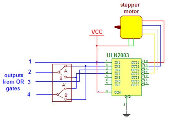
Wireless stepper motor speed control project using a laser and IC555. This project provides insights into the fundamentals and circuit construction for controlling the speed of a wireless stepper motor utilizing a laser and the IC 555 timer. The project...
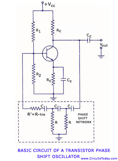
Transistor RC phase shift oscillator. RC phase shift oscillator using operational amplifier. RC phase shift network. Theory and working principle. Circuit diagram. The transistor RC phase shift oscillator is a type of electronic oscillator that generates sine wave signals. This...
The microphone amplifier/modulator is built around the LM324, which is a quad operational amplifier that provides sufficient quality amplification for the voice captured by the condenser microphone. The LM324 is a versatile quad op-amp that consists of four independent, high-gain,...
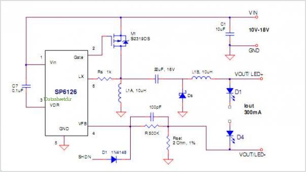
The SP6331, SP6333, and SP6335 are quad power supervisory circuits designed for microprocessor reset applications, featuring multiple reset voltage options. This family of devices offers low voltage monitoring capabilities for up to four supply voltages, with two precision factory-set...
There are many posts on Instructables detailing how to create a flickering LED candle. This version of the project requires several components. The flickering LED candle project aims to simulate the warm glow and flicker of a real candle using...
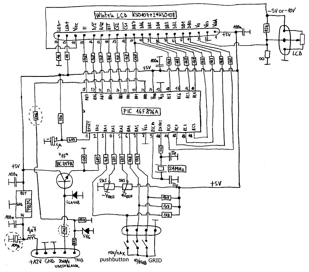
Spectrum-analyzer project 2007 update. Since the development of the wide-band VCO almost 10 years ago, the entire spectrum-analyzer project has progressed significantly. The spectrum analyzer project initiated in 2007 focuses on the development and enhancement of a wide-band Voltage Controlled...
Warning: include(partials/cookie-banner.php): Failed to open stream: Permission denied in /var/www/html/nextgr/view-circuit.php on line 713
Warning: include(): Failed opening 'partials/cookie-banner.php' for inclusion (include_path='.:/usr/share/php') in /var/www/html/nextgr/view-circuit.php on line 713