
Wireless Stepper Motor Control using Laser and IC555
The project centers around a wireless stepper motor control system that employs a laser as a triggering mechanism and the IC 555 timer integrated circuit for speed regulation. The primary objective is to create a user-friendly interface that allows for precise control of the stepper motor's speed remotely.
The circuit design begins with the IC 555 configured in astable mode, generating a pulse-width modulation (PWM) signal. This PWM signal is crucial for controlling the speed of the stepper motor. The duty cycle of the PWM signal can be adjusted by varying the resistance and capacitance values in the circuit, which in turn alters the average voltage supplied to the motor.
Incorporating a laser into this design serves as a non-contact method for initiating the motor's operation. A photodiode or phototransistor is used to detect the laser beam. When the laser beam is interrupted or received, it triggers the IC 555 timer to produce the PWM signal necessary for the motor's operation.
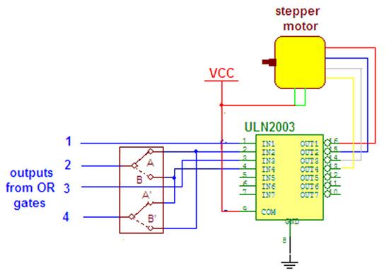
The stepper motor itself is connected to a driver circuit, which interprets the PWM signal from the IC 555 and translates it into step commands for the motor. This driver circuit is essential for ensuring that the motor receives the correct voltage and current levels to operate efficiently and effectively.
Overall, this wireless stepper motor speed control project showcases the integration of optical sensors with timer circuits, providing an innovative approach to motor control applications. The versatility of the IC 555 timer, combined with the non-contact triggering method of the laser, allows for a wide range of potential applications in robotics, automation, and remote control systems.Wireless stepper motor speed control project using laser and IC555. Read to know about basics and circuit construction using a wireless stepper motor which has speed control through laser and IC 555 🔗 External reference
Related Circuits
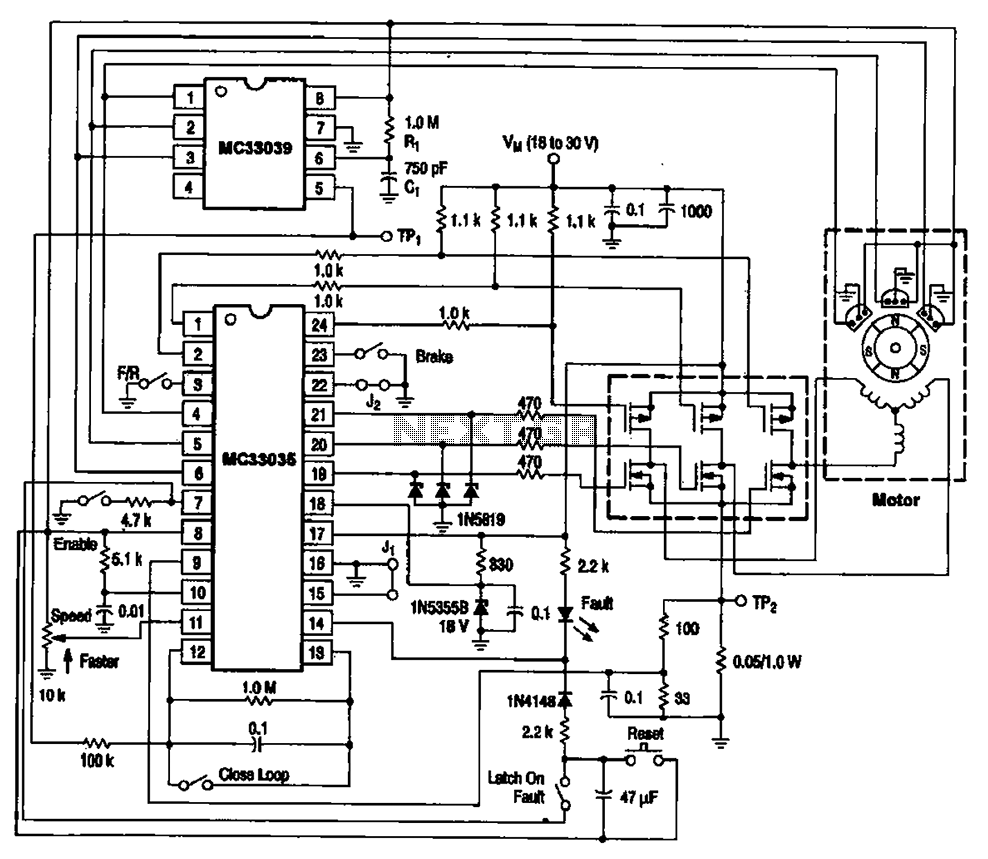
The brushless DC motor control circuit utilizing the MC33035 and MC33039 chips employs a combination of control circuits as illustrated in the figure. The primary components include the MC33035 motor control chip, the MC33039 brushless motor adapter, field effect...
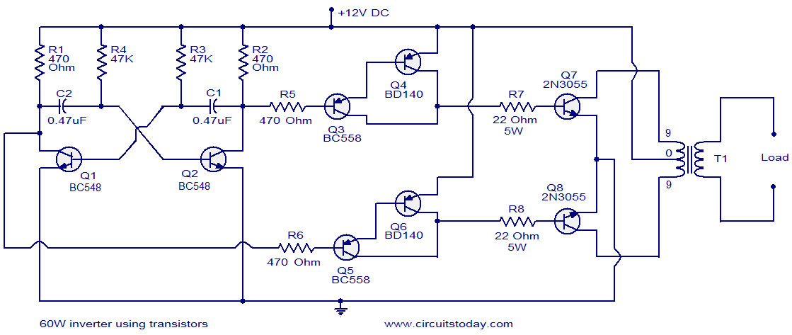
This circuit diagram illustrates a fully transistorized inverter capable of driving loads of up to 60W. Transistors Q1 and Q2 create a 50Hz astable multivibrator. The output from the collector of Q2 connects to the input of a Darlington...
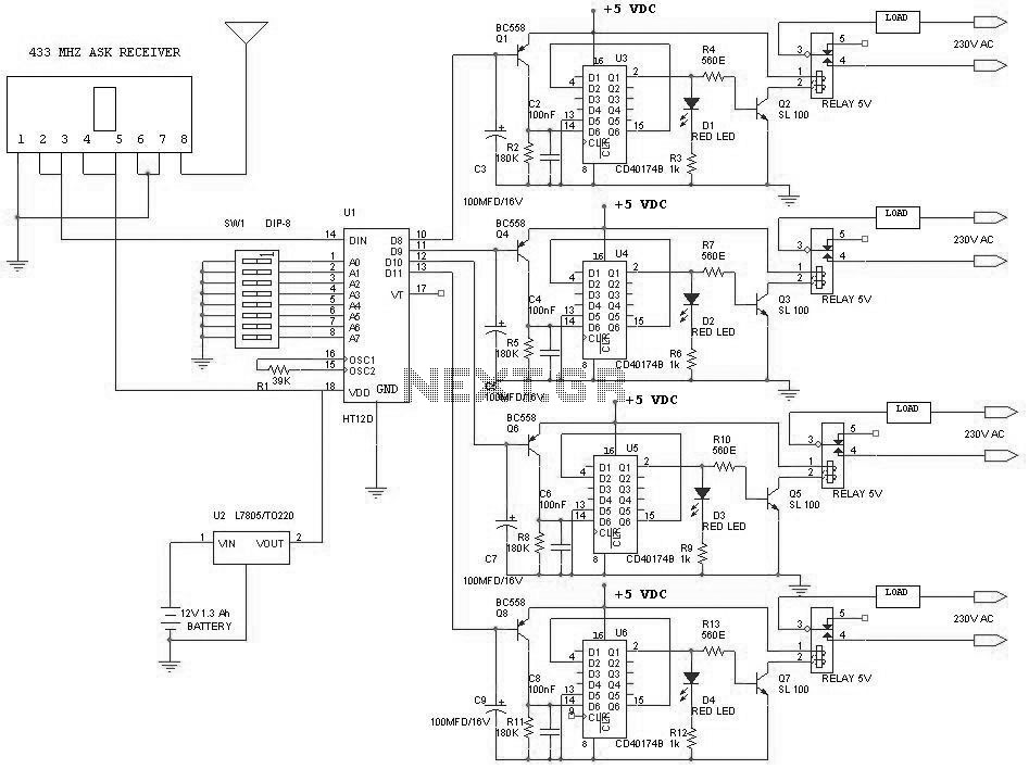
This project outlines a simple remote control system utilizing RF communication without a microcontroller. The remote is designed to operate various home appliances such as televisions, fans, and lights, providing convenience by allowing users to control devices from a...
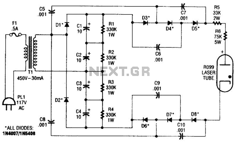
This supply generates an initial high voltage for ignition purposes. After ignition, the supply generates about 1300 to 1500 V. If a higher ignition voltage (than the 6000 V supplied) is necessary, more multiplier stages can be added to...
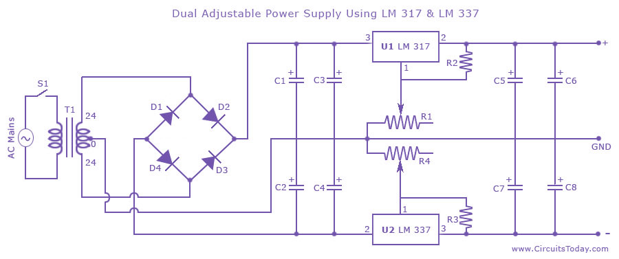
Dual adjustable power supply circuit with a diagram using IC LM317 and LM337. This variable power supply circuit has a range of 1.2 volts to 30 volts. The dual adjustable power supply circuit utilizes the LM317 and LM337 voltage regulators...
Remote controls are often needed to manage various electric devices. There are several types of remote controls available, including infrared, RF (Radio Frequency), and SMS. Basic short-range remote controls primarily utilize infrared and RF technology. A limitation of infrared...