
Flickering LED Candle using Tiny45
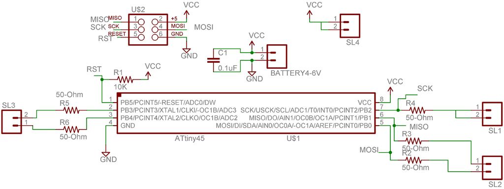
The flickering LED candle project aims to simulate the warm glow and flicker of a real candle using electronic components, providing a safe alternative to traditional candles. The essential components for this project typically include a microcontroller (such as an Arduino), an LED (preferably warm white or yellow), a resistor, a power source (like batteries), and a small breadboard or PCB for assembly.
The microcontroller serves as the heart of the project, controlling the LED's brightness and flickering effect through pulse-width modulation (PWM). The LED is connected in series with a resistor to limit the current and prevent damage. The power source can be a battery pack, ensuring portability and ease of use.
To create the flickering effect, the microcontroller is programmed to vary the LED's intensity in a manner that mimics the natural flicker of a candle flame. This can be achieved by randomly adjusting the brightness level at short intervals, using a combination of analogWrite functions (for PWM control) and random number generation to create an unpredictable flickering pattern.
The assembly of the circuit involves connecting the LED and resistor to the microcontroller's output pin, while the power source is connected to the microcontroller's power input. Proper soldering or breadboarding techniques should be employed to ensure reliable connections.
Safety considerations include ensuring that the circuit operates at low voltage and current levels to prevent overheating and potential hazards. The final product can be housed in a decorative holder that resembles a traditional candle, enhancing the aesthetic appeal while maintaining the functional safety of an LED-based light source.There are numerous posts on Instructables about how to make a flickering LED candle. This is my version. The project requires the following components. 🔗 External reference
Related Circuits
The PR4403 is an advanced version of the PR4402 40mA LED driver. It features an additional input known as LS, which can be activated by pulling it low to illuminate the LED. This functionality simplifies the construction of an...
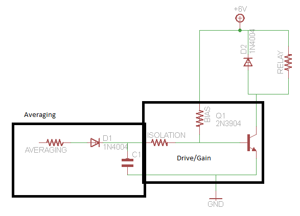
A circuit that activates a relay upon detecting audio pulses from one channel of an MP3 player. The intention is to synchronize recorded audio pulses with music to control a motor for mouth movement. For a stereo player, music...
This flip-flop circuit is a free-running astable multivibrator, with the bases and collectors of both emitter-biased transistors directly coupled to each other. The switching action is facilitated by a capacitor in each emitter circuit. This configuration produces triangular waves...
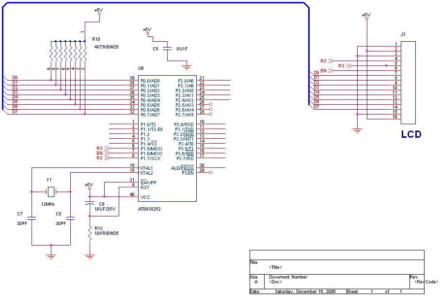
How to interface an LCD to the 89C51 microcontroller using 4-bit mode. A Lampex 16200 controller is being used; please send the manual for this controller. To interface an LCD with the 89C51 microcontroller using 4-bit mode, the following steps...
Mobile batteries typically have a lifespan of 2 to 5 years under normal usage, after which they need to be replaced. Currently, inexpensive replacement batteries are available for about $1, but these low-cost options only last 6 to 12...
The Tiny Remote is a compact infrared remote control featuring only two buttons designed to operate an iRobot Roomba. It emits three different infrared signals. The Tiny Remote is designed for simplicity and ease of use, making it an ideal...
Warning: include(partials/cookie-banner.php): Failed to open stream: Permission denied in /var/www/html/nextgr/view-circuit.php on line 713
Warning: include(): Failed opening 'partials/cookie-banner.php' for inclusion (include_path='.:/usr/share/php') in /var/www/html/nextgr/view-circuit.php on line 713