
Vacuum Tube Direct Interface
The implementation of this system requires careful attention to the design of the triaxial cable and connectors, ensuring compatibility and optimal performance. The use of high-quality materials for the inner and outer shields, as well as the center conductor, is essential to maintain signal integrity and minimize losses. Additionally, the circuit design should incorporate appropriate filtering and amplification stages to enhance the signal without introducing unwanted noise or distortion. The choice of components, including the FET or BJT used in the follower or amplifier configuration, plays a crucial role in achieving the desired performance characteristics. A thorough understanding of the electrical properties of the materials used, as well as the specific requirements of the musical instrument, is necessary to create an effective solution that meets the needs of musicians while preserving the integrity of their sound.Requires that DC power be brought into the instrument, either through special cabling or an internal battery. Should not be done to collectible instruments if they didn`t come with onboard electronics. Conveniently implemented as a field effect transistor (FET) or bipolar junction transistor (BJT) follower, or perhaps an amplifier with modest gain.
Can drive any impedance input, while eliminating stray capacitance in cabling and connectors. First made popular by Alembic in the late `60s and Music Man in the `70s. Active electronics inside the cable. Next best solution, allows a simple follower or amplifier to be placed very close to the instrument, for instance inside the plug backshell at the instrument end of the cable. Can drive any impedance input, while eliminating stray capacitance except for one plug and one jack. The instrument itself is unmodified. I have previously developed solutions of this type, which I call Active Plug technology. So-called "Active Cable" solutions are also commercially available. High input impedance amplifier. This is usually the least desirable solution, as it takes no account of cable capacitance. For some artists, of course, the cable is part of their sound and shouldn`t be messed with. But in applications where the desired signal is the voltage source inside the pickup, this just won`t do.
Unless, that is, a way can be found to cancel out the cable capacitance. The remainder of this page describes a solution I`ve developed which does just that. Coaxial cable is commonly available and universally used for musical instrument pickups, often with 1/4" phone plugs on each end. But did you know that triaxial cable is also available Like coaxial cable, the triaxial form has an inner center conductor and an outer braided shield, but it also has an inner braided shield which is electrically isolated from both the center conductor and the outer shield.
What you do with the inner shield is up to you, but in simple applications you could connect it to the outer shield resulting in a conventional coaxial cable, or you could use it to carry the pickup ground separate from earth ground to overcome ground loops. But what I have done is to drive the inner shield with a signal which is nearly identical in phase and amplitude to the pickup signal.
So the center conductor and the inner shield are carrying the same signal and have no potential difference between them. The result of this is that no charge is stored in the inner dielectric, and the capacitance seen by the center conductor is essentially zero.
When used with triaxial plugs and jacks meant to go with this type of cable, stray capacitance due to cable and connectors can be made arbitrarily small. This may sound like you are getting something for nothing, but what is actually happening is that the pickup signal on the center conductor is amplified, not in voltage but in current, before it is used to charge the outer dielectric, between inner and outer shields.
This represents a very large capacitance, much larger than the capacitance from center conductor to inner shield, but t 🔗 External reference
Related Circuits

ECL integrated circuit non-saturated digital logic circuits. CMOS and ECL interface circuit shown in cross. ECL (Emitter Coupled Logic) integrated circuits are designed to operate in a non-saturated mode, providing high-speed digital logic functionality. These circuits are characterized by their...
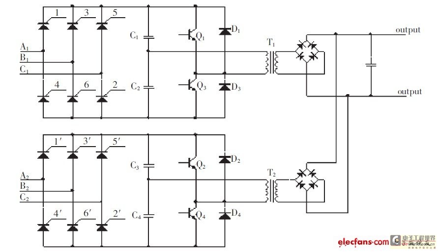
The high-pressure direct current power supply has become increasingly widespread. This system outputs in parallel with double-channel power to achieve low ripple direct current. In situations where gas switching tube frequency is limited, this method can generate low ripple...
A LED is defined as "light-emitting diode: diode such that light emitted at a p-n junction is proportional to the bias current; color depends on the material used." As the LED is a diode, it doesn't conduct electricity in...
Build a CD47 Nixie Clock. Power: approximately 100 Watts. Some may question if this is over-engineered, but it will be justified by the project's outcome. The Nixie tubes will be turned off when not in use to prolong their...
This circuit is a modified version of an original interface on QSL Net. It is a fully isolated interface allowing computer control of the Trio/Kenwood R5000 receiver. Separate software is needed to control the receiver. The R5000 receiver is...
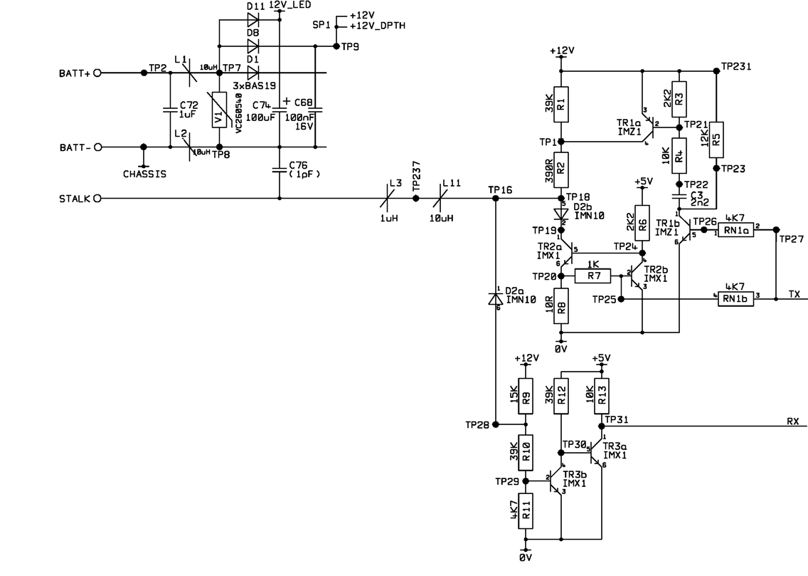
A project involves using a PIC microcontroller to communicate with the Raymarine SeaTalk bus. The schematic diagram for a Raymarine instrument shows a logic chip connected to the TX and RX connections on the right side, while the SeaTalk...