
CD47 (Rodan) Nixie Tube Clock
 Nixie Tube Clock")
The CD47 Nixie Clock project integrates several advanced technologies to create a visually appealing and functional timepiece. The primary power requirement of approximately 100 Watts indicates a robust design capable of supporting the high voltage needs of the Nixie tubes, which operate at around 170V. The decision to implement a standby mode enhances the longevity of the Nixie tubes by minimizing their operational time when not in use.
The use of ECM and radar sensors for activation based on sound and movement is innovative, allowing for a responsive user experience. The ECM will detect acoustic signals, while the KMY24 radar sensor will utilize the Doppler effect to identify motion. The design includes a DC-DC converter to ensure that both sensors receive the necessary power, which is essential for maintaining continuous operation and responsiveness.
The adjustable output voltage feature, controlled by a potentiometer during initial testing and later by PWM modulation through the microcontroller, allows for precise tuning of the Nixie tubes' brightness and performance. Additionally, the implementation of octal D-type transparent latches (74HC373) enables efficient control of multiple outputs, facilitating the management of both the Nixie tubes and the colon tubes.
The circuit design includes multiple operational amplifier stages for signal processing, ensuring that the outputs from the radar sensor are clean and suitable for digital processing by the microcontroller. The use of filters in conjunction with a differential amplifier enhances the detection capabilities of the radar sensor, allowing it to accurately discern movement and trigger the Nixie tubes accordingly.
Overall, the CD47 Nixie Clock project exemplifies a blend of traditional clockmaking with modern electronic components, resulting in a sophisticated device that is both functional and aesthetically pleasing. The careful consideration of power management, signal processing, and output control ensures a reliable and efficient operation, making it a noteworthy addition to any electronics enthusiast's collection.Build a CD47 Nixie Clock. Power: approx. 100 Watts (some might say "Isn`t it over- engineered", but you`ll see at the end of that project, that it`s ok. Nixies will be switched off when nobody is around- this will keep them alive as long as possible. The sensors for the detection will be a ECM (microphone) and a radar sensor. As you can see there is nothing to adjust, but the output voltage 170V. This can be done by a pot for the test- phase, and later by the CPU by PWM- modulation. I started this website arter already made the experiments with the supply, so I unfortunately have no pictures of the experiments. The output voltage is adjustable from 160 to 180 Volts by the pot (later by the CPU). The Stand- By- Mode also works perfect. When switched to stand by, the 5V- CPU voltage shows no voltage drop, not even any move of the meter.
You can short any output, you can leave the output open, you can do what you want. It works. The CD47 tubes may be switched on, when a noise occurs (door opened, TV turned on or something like this). I developed a simple sonic- sensor with an ECM which will be connected to the controller (analog input).
I first planned to let it work on the 5V- stand- by- power. But as I use a radar sensor, which needs 12V to work, I planned a small DC-DC (5 to 12V) for the Radar- Sensor and for the Acoustic- Sensor. The CD47 tubes may be switched on, when a movement occurs (door opened, people moving around or something like this).
This I`ll solve with a Radar- sensor which will be connected to the controller (digital input). The KMY24 is a radar- sensor which uses the doppler effect. It`s simple to use and provides 2 phase- shifted doppler- signals. The signals run through some filters. As you can see, the first OP Stage is a typical differential amplifier. The second stage also a filter, and the third stage is just an impedance-transformer. R82 adjusts the sensitivity. The output provides the 0/5V rectangular signal for the Microcontroller. I`ll take 8 octal D-type transparent latches type 74HC373 and connect a smd- resistor and a high voltage SMD- transistor to every output- so I get 64 outputs. 60 I use for the cathodes an 4 for the colon- tubes. The colon- tubes are not developed, yet. I made a quick `rats-nest` experiment, which worked excellent: 🔗 External reference
Related Circuits
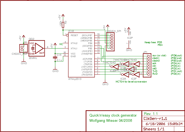
The design generates varying sampling clock write strobe pulses using an ATtiny2313 microcontroller from Atmel. For a 10MHz sampling clock, a 20MHz clock is required for the ATtiny2313, necessitating a power supply of 5V instead of 3.3V, which is...
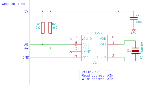
The Arduino displays the time and date on an optional LCD and in the Arduino IDE serial monitor window. A PCF8563 real-time clock (RTC) integrated circuit (IC) is utilized to generate the time and date. The time and date...
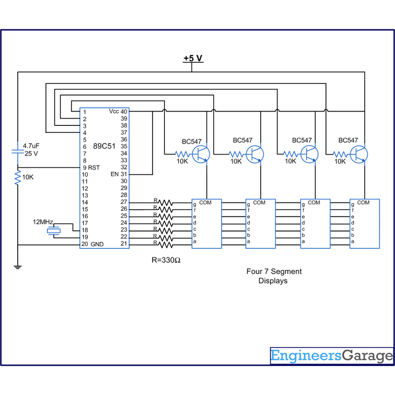
A digital clock displays time in a digital format. The circuit outlined here shows the time with double-digit minutes and two digits for seconds across four seven-segment displays. The segments of the displays are interconnected with the 8051 microcontroller...
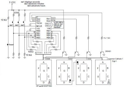
A digital clock project utilizing the PIC16C54 microcontroller can be constructed using the provided circuit diagram. This electronic project features a straightforward time-of-day clock that includes four seven-segment LED displays and three input switches, along with an additional reset...
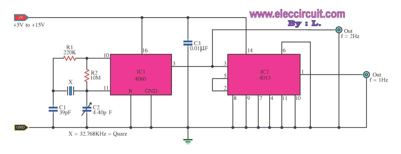
This is a standard digital clock circuit with a frequency of 1 Hz or 2 Hz. It can be utilized in a conventional clock circuit. The circuit comprises IC-4060 and IC-4013. The digital clock circuit operates by generating a precise...
This phono stage significantly outperformed a sub-mini phono preamp. The phono preamp was exceptionally quiet when paired with a vintage Grado 8MR cartridge (not MC). It does not have a vintage sound; while it is pleasant and clearly tube-based,...