
Vacuum Tube Tesla Coil (VTTC

The Tesla Coil is a resonant transformer circuit that generates high-voltage, low-current, high-frequency alternating current electricity. It operates on the principles of electromagnetic induction and resonance. The basic components of a Tesla Coil include a primary coil, a secondary coil, a power supply, a spark gap, and a capacitor.
The primary coil consists of a few turns of heavy gauge wire, which is connected to a capacitor that forms a resonant LC circuit with the coil. When the power supply is activated, the capacitor charges and discharges through the primary coil, creating a magnetic field. The secondary coil, which has many more turns of finer wire, is placed within the magnetic field of the primary coil. Due to the principle of mutual induction, the energy from the primary coil induces a voltage in the secondary coil.
The spark gap is a crucial component that allows the circuit to oscillate. It acts as a switch that opens and closes rapidly, allowing the energy stored in the capacitor to discharge into the primary coil. The frequency of oscillation is determined by the values of the capacitor and the inductance of the primary coil.
To ensure safe operation, proper insulation and grounding techniques must be employed. The high voltage generated can be dangerous, requiring careful handling and precautions. Additionally, the design can be optimized for performance by adjusting the turns ratio between the primary and secondary coils, as well as the values of the capacitor and spark gap.
Overall, the Tesla Coil is a fascinating example of electrical engineering, demonstrating principles of resonance and electromagnetic fields in action.Here is the particular schematic for the Tesla Coil that we will be building. I do not take credit for its creation - it was made by Steve Ward and yo.. 🔗 External reference
Related Circuits
Here is a Tesla coil secondary design: Wind 750 turns of 24-gauge enameled magnet wire onto an 18-inch long piece of 1.9-inch outer-diameter PVC pipe. The large coil has an inductance of approximately 2800 mH and a self-capacitance of...
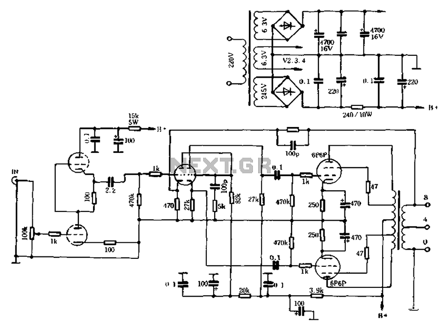
The self-generated bias amplifier tube is designed for each tube individually to alleviate the challenges faced by amateur conditions in paired amplifiers. It includes a separate DC filament power supply, which minimizes the risk of induced cross-linking and enhances...

An inverter circuit is designed to power electroluminescent (EL) backlights and fluorescent tubes, producing an output of approximately 127 VAC. However, the objective is to achieve an output of 1 kV or more to generate at least 1 mm...
A method to increase the wattage of a small-scale Tesla coil is being sought. The current output from the secondary coil is not satisfactory. Although the specific current and voltage values are unknown, it is observed that the coils...
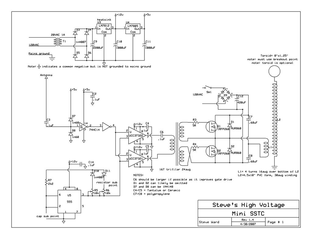
This instructable provides detailed instructions for constructing a solid-state Tesla coil based on Steve Ward's mini SSTC schematic. The solid-state Tesla coil (SSTC) is an advanced high-frequency resonant transformer that operates without the need for mechanical components such as spark...
To design a Tube Headphone Amplifier we need a triode with uncommon characteristics: enough voltage gain, low internal resistance and good anodic current. My first test was done with the E182CC, but there is the limitation on the usable...