
Tesla Coil Wattage Boost

To enhance the wattage output of a small-scale Tesla coil, several modifications can be considered. The fundamental parameters influencing the performance of a Tesla coil include the resonant frequency, the coupling between the primary and secondary coils, and the input power supply characteristics.
1. **Resonant Frequency Tuning**: It is crucial to ensure that the primary and secondary coils are well-tuned to resonate at the same frequency. This can be achieved by adjusting the number of turns on the coils or by modifying the capacitor in the primary circuit. Using a variable capacitor can allow fine-tuning of the resonant frequency to optimize energy transfer.
2. **Improving Coupling**: The coupling coefficient between the primary and secondary coils significantly impacts the energy transfer. Increasing the coupling can be done by reducing the distance between the coils or by adjusting their alignment. A tighter coupling can lead to a more efficient transfer of energy, thereby increasing the output wattage.
3. **Power Supply Enhancement**: The input power supply plays a critical role in the performance of the Tesla coil. Increasing the input voltage or current can lead to higher output wattage. This may involve using a more powerful transformer or a higher voltage power supply, ensuring that all components can handle the increased power levels safely.
4. **Capacitor Selection**: The capacitor in the primary circuit should be chosen carefully to handle the expected voltage and energy levels. A capacitor with a higher voltage rating and appropriate capacitance value can store more energy, leading to a more powerful spark output.
5. **Spark Gap Optimization**: The spark gap's configuration can also affect performance. Adjusting the distance between the electrodes can change the breakdown voltage, allowing for a more efficient discharge. Additionally, using a rotary spark gap can provide more consistent and higher frequency discharges.
6. **Secondary Coil Modifications**: Consider using a secondary coil with a larger diameter or more turns to increase the output voltage. The wire gauge should also be appropriate to minimize resistive losses.
7. **Load Considerations**: The load connected to the output of the Tesla coil should be considered. A load that is too high may draw excessive current, leading to reduced performance. Ensuring that the load is matched to the output capabilities of the coil can improve efficiency.
Implementing these modifications requires careful consideration of component ratings and safety precautions due to the high voltages involved. Testing should be conducted incrementally to observe the effects of each change on the output performance of the Tesla coil.A way to boost the wattage of my small scale Tesla coil. I`m not getting good wattage going coming off the secondary. I`m not sure what the current or voltage is but from what i can tell is that the coils are resonant and that the output is like 100kv at probably half a mA. But back to the main question is there any way i can tweak the circuit to get higher wattage This is the circuit I`m using right now:
🔗 External reference
Related Circuits
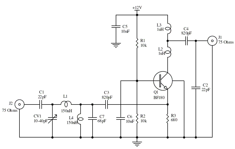
This is a UHF band TV antenna preamplifier circuit with a gain of 15 dB. It is designed using the BF180 UHF transistor. The input stage consists of a band-pass filter implemented with components C1, CV1, L1, L4, C7,...
Continuing the studies on directly coupled multiple resonance networks operated as Tesla coil-like devices, a 6th-order system was constructed that is equivalent to a "Tesla magnifier," but without a transformer. The schematic diagram is provided. This circuit has several...
A DC-to-DC step-up converter is typically implemented using a transformer, which converts DC voltage to AC voltage, steps it up with the transformer, and then rectifies and filters the output to achieve a higher DC voltage. However, a voltage...
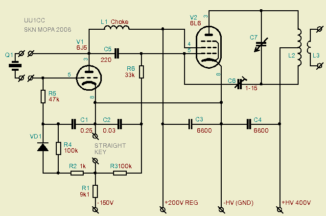
A Pierce "aperiodic" oscillator drives a non-neutralized power amplifier for a multiband Morse code transmitter that requires only one coil and minimal adjustment. This document examines the topology of the Boosted Pierce oscillator, tracing its evolution from its origins...
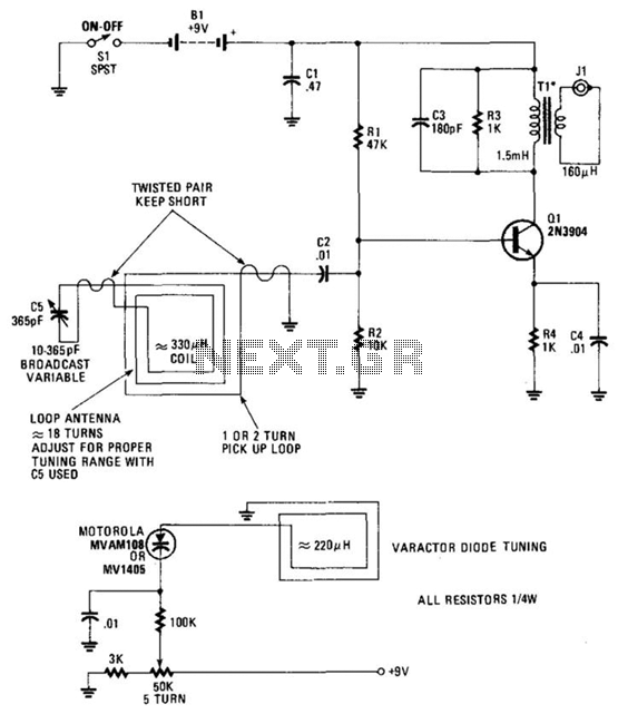
The use of a large loop antenna (12 to 18 inches) facilitates significant signal reception at AM broadcast frequencies. It consists of approximately 18 turns. Tl is a toroidal transformer with an approximate 3:1 turns ratio (non-critical). The primary...

Four 4.8 Volt 2000mA Nickel Cadmium batteries require a safe method for initial charging using a lab power supply, as a specific NiCad charger is not available. Assistance is sought for circuit drawings of a simple NiCad charger. The...