
Vacuum tube tesla coil (VTTC) using Russian GU-81m
 using Russian GU-81m")
To ensure the reliability and performance of the coil, the additional turns increase the inductance, which may enhance the coil's functionality in its intended application. However, with the increase in turns, there is a corresponding increase in the risk of electrical breakdown due to reduced dielectric strength in the insulation. Therefore, the use of epoxy as an insulating material is a prudent choice, given its excellent electrical properties and ability to provide a robust barrier against moisture and other environmental factors.
The application of epoxy over the soldered areas serves multiple purposes. Firstly, it protects the solder joints from mechanical stress and potential corrosion, which can occur over time due to environmental exposure. Secondly, the epoxy provides a uniform dielectric layer that minimizes the risk of arcing between the coil windings, enhancing the overall safety and longevity of the component.
When applying epoxy, it is important to ensure that the surface is clean and free from contaminants to achieve optimal adhesion. The curing process should be monitored to ensure that the epoxy fully hardens, providing a solid and reliable insulation layer. Additionally, consideration should be given to the thermal properties of the epoxy, as excessive heat can affect its insulating capabilities.
In summary, the modifications made to the coil through the addition of turns and the application of epoxy insulation significantly enhance its performance and reliability, making it suitable for a variety of electronic applications where robust insulation and durability are required.The coil has been added a few extra turns, so I had to find a way to improve the insulation. I opted for epoxy, with some extra quantity added over the soldering: 🔗 External reference
Related Circuits
This standalone digital thermometer regulates the temperature of a device based on its requirements. It displays the temperature on four 7-segment displays, with a range from 55 to +125 °C. The core of the circuit is the AT89S52 microcontroller,...
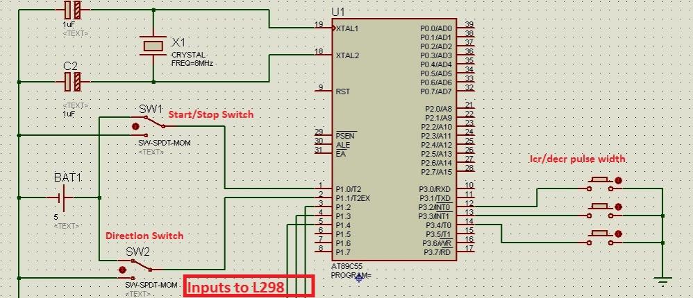
Greetings to all! A new user is exploring microcontrollers and is utilizing the AT89C55WD microcontroller to control an H-Bridge (L298), which subsequently drives a DC motor. The circuits for this setup are... The AT89C55WD microcontroller is an 8-bit microcontroller from...
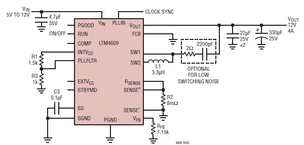
A very simple, high-efficiency switching mode buck-boost power supply circuit can be designed using the LTM4609 switching regulator IC. This circuit will provide a fixed output voltage of 12 volts. As illustrated in the schematic, the switching power supply...
The first example utilizes a standard op-amp oscillator circuit to produce a triangular waveform, which is then level-shifted and supplied to a comparator (e.g., LM339) to generate a PWM waveform. It is common for users to prefer using two...
To design a Tube Headphone Amplifier we need a triode with uncommon characteristics: enough voltage gain, low internal resistance and good anodic current. My first test was done with the E182CC, but there is the limitation on the usable...
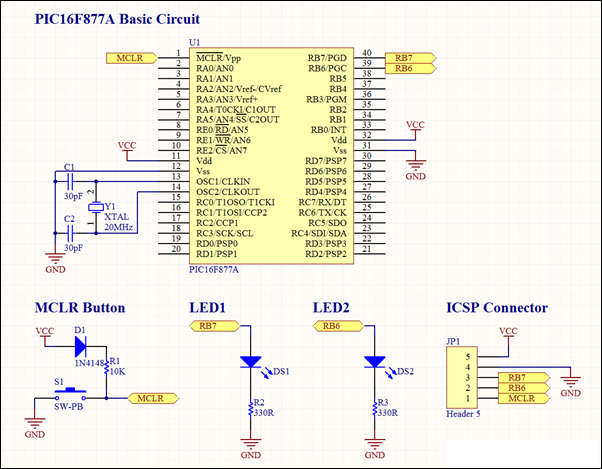
This project involves a basic LED blinking circuit utilizing the PIC16F877A microcontroller. It features two LEDs connected to the PIC16F877A, with the source code adapted from the 16F template. The circuit design consists of the PIC16F877A microcontroller, which serves as...