
Pulse Width Modulators using LM339
The described circuit employs an operational amplifier (op-amp) configured as an oscillator to generate a triangular waveform. This waveform serves as the basis for pulse-width modulation (PWM) signal generation. The triangular waveform is level-shifted to ensure it operates within the appropriate voltage range for the subsequent comparator stage. The comparator, such as the LM339, is utilized to compare the triangular waveform against a reference voltage.
In this configuration, two comparators are employed to enhance performance and flexibility. The first comparator is responsible for determining the rising edge of the PWM signal, while the second comparator manages the falling edge. This dual-comparator setup allows for more precise control over the duty cycle of the PWM signal.
The triangular waveform is generated by the op-amp in an astable multivibrator configuration, where the feedback network sets the frequency of oscillation. The output of the op-amp is then level-shifted using a simple resistor network or a dedicated level-shifting circuit, ensuring that the voltage levels are compatible with the input requirements of the comparators.
The output from the comparators produces a PWM waveform, which can be utilized in various applications such as motor control, dimming of LED lights, and other power modulation tasks. The duty cycle of the PWM signal can be adjusted by varying the reference voltage applied to the comparators, thus providing a method to control the average power delivered to the load.
This circuit exemplifies a robust approach to generating PWM signals, leveraging the characteristics of op-amps and comparators to achieve effective signal modulation.The first example uses the standard op-amp oscillator circuit to generate a triangular waveform which is level-shifted and fed to a comparator (e. g. LM339) to give the PWM waveform. Most people will want to use two comparators rather than one op-amp and one comparator so that is what we show here.
Disclaimer All files are found using legitimate se arch engine techniques. This site does not and will not condone hacking into sites to create the links it list. We will and do assume that all links found on the search engines we use are obtained in a legal manner and the webmasters are aware of the links listed on the search engines. If you find a URL that belongs to you, and you did not realize that it was "open to the public", please use the report button to notify the blogmaster of your request to remove it or it will remove within 24 hours.
This is not an invitation for webblog haters to spam with requests to remove content they feel that is objectionable and or unacceptable. Proof of URL ownership is required. NOTICE: This Blog Has Already Been Reviewed And Accepted By Blogger. com 🔗 External reference
Related Circuits
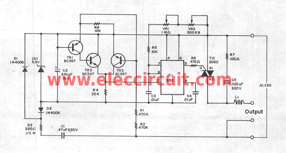
The super dimmer is an improved version compared to the standard dimmer currently in use. Testing its performance will provide a clearer understanding of its advantages. The super dimmer operates using advanced technology that allows for finer control over...
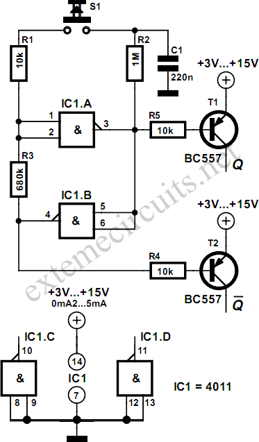
Using just two NAND or inverter gates, it is possible to build a D-type (or toggle) flip-flop with a push-button input. At power-up, the output of gate N2 is at a logical 1, ensuring that transistor T2 is switched...
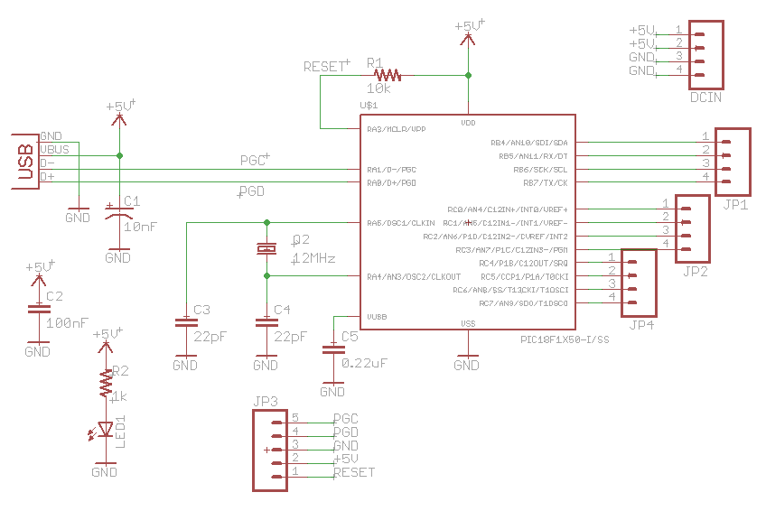
The character data and command from the microcontroller is transferred serially to a shift register (74HC595), and the parallel output from the shift register is fed to LCD pins. 74HC595 is a high-speed 8-bit serial in, serial or parallel-out...
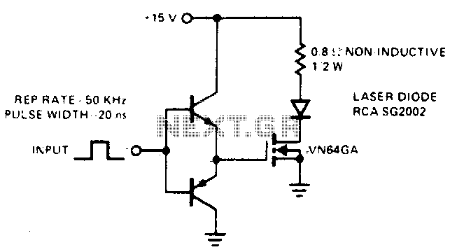
This drive is capable of supplying the laser diode with 10 ampere pulses lasting 20 ns. With a 0% duty cycle, the repetition rate is 50 kHz. A complementary emitter-follower configuration is utilized as a driver. Switching speed is...
A schematic diagram of a fast pulse detector is shown in the figure below. An error detection rate of under 10% can be expected for a 60 ns pulse to achieve error-free operation. The fast pulse detector circuit is designed...
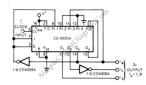
This is a schematic diagram of a three-phase pulse generator circuit. This circuit produces a three-phase overlapped output similar to a three-phase AC power line. The three-phase pulse generator circuit is designed to create three-phase output signals that are phase-shifted...