
DC motor speed control using 8051 and l298
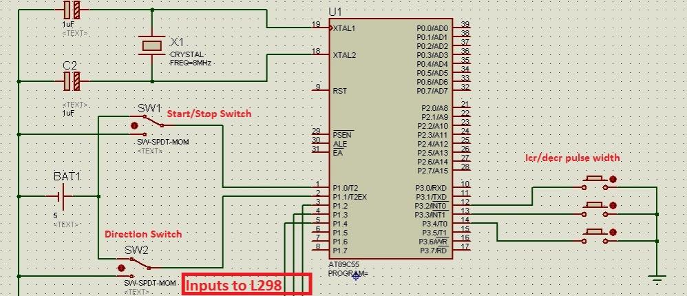
The AT89C55WD microcontroller is an 8-bit microcontroller from the 8051 family, featuring a 40-pin dual in-line package (DIP) design. It is equipped with 32 I/O lines, two 16-bit timers/counters, and a full-duplex UART for serial communication. This microcontroller is well-suited for applications requiring precise control and interfacing with various peripherals.
In this application, the AT89C55WD interfaces with an L298 H-Bridge driver. The L298 is a dual H-Bridge motor driver capable of driving two DC motors or one stepper motor. The H-Bridge configuration allows for bidirectional control of the motors, enabling forward and reverse operation. The L298 can handle up to 2A of continuous current per channel and is suitable for motors operating at voltages ranging from 5V to 46V.
The circuit design involves connecting the output pins of the AT89C55WD to the input pins of the L298. Typically, four control pins are used to manage the two motors: two for each motor's direction and two for enabling the motors. PWM (Pulse Width Modulation) signals can be generated by the microcontroller to control the speed of the DC motors by varying the duty cycle of the signals sent to the enable pins of the L298.
Power supply considerations are critical in this setup. The microcontroller should be powered with a stable voltage, typically 5V, while the L298 should be connected to a suitable power source that matches the motor's voltage requirements. It is also advisable to include decoupling capacitors near the power pins of both the microcontroller and the L298 to filter out noise and ensure stable operation.
In summary, this configuration leverages the AT89C55WD microcontroller's capabilities to control an L298 H-Bridge driver, allowing for effective management of DC motors in various applications, including robotics and automation systems. Proper circuit design and component selection are essential for achieving reliable performance in the intended application.Hi Everyone out there! I am new to microcontrollers. I am using AT89C55WD to control H-Bridge (L298) which in turn drives the DC motor. Circuits for.. 🔗 External reference
Related Circuits

The circuit below demonstrates the generation of a single positive pulse that is delayed in relation to the trigger input time. It is similar to a previously described circuit but utilizes two stages, allowing for control over both the...
At high speeds, visually checking the speedometer to remain under the maximum speed can be hazardous. Implementing an audio alarm system would enhance safety by providing auditory alerts. To enhance vehicle safety at high speeds, an audio alarm system can...
This document presents an electronic project focused on device control using a timer. This circuit allows for the activation of an appliance at a specified time for a predetermined duration. It can be applied to manage the operation of...
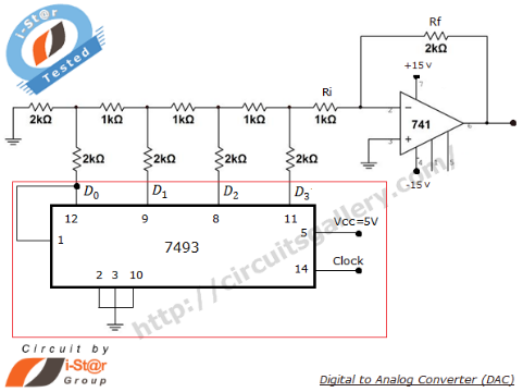
A Digital to Analog Converter (DAC) is utilized to produce an analog voltage that corresponds to input digital data. Binary data can be transformed into its analog equivalent using an R-2R ladder network combined with a summing amplifier, which...
A soft power switch for a microcontroller is designed such that a momentary switch can activate the circuit, including the microcontroller. When the switch is pressed a second time, the microcontroller is capable of shutting itself down after executing...
A switch that is controlled by its ambient temperature operates without human intervention, except during the assembly of the electronic thermostat. This thermally controlled switch has numerous practical applications. For instance, if the internal temperature of a computer rises...