
Operational Amplifier Voltage Comparator Circuits

A voltage comparator functions primarily by comparing two input voltages and outputting a signal that indicates which input is greater. The device operates effectively within a range of voltages defined by the specific model and its power supply. Common applications include signal conditioning, level detection, and zero-crossing detection, where the comparator can determine when an input signal crosses a predefined threshold.
The LM339 comparator, a widely used component, features an open-collector output, necessitating an external pull-up resistor to establish the desired output voltage level. This flexibility allows the output to interface with various logic families, making it suitable for diverse electronic applications. The choice of pull-up voltage can be tailored to the requirements of the connected circuitry, whether it be standard TTL logic levels or lower voltage systems.
In terms of packaging, the LM339 is available in multiple formats, including DIP and SOIC, allowing for integration into various circuit designs. The 14-pin configuration provides ample space for multiple comparators on a single chip, enhancing design efficiency. Proper handling of unused inputs is crucial to prevent unintended behavior, and connecting these inputs to the negative supply ensures stable operation.
Overall, the voltage comparator is a versatile and essential component in modern electronic design, offering straightforward voltage comparison capabilities while interfacing seamlessly with digital logic systems.A voltage comparator is a device that compares the voltage at the two inputs and develops an output based on the inputs. A high output when the plus input is greater than the minus input or a low output when the plus input is less than the minus input.
A comparator is a component that compares the two analog inputs and outputs a digital signal tha t represents which input signal is greater than the other. An acceptable analog input depends on the actual voltage comparator used and the voltage used to power it. The digital output can be almost any digital signal and again depends on the comparator and the voltage used to power it.
However; the outputs might include an Open Drain, Open Collector, TTL Totem Pole, LVDS, or Push-Pull, to list the most common. So even though the input is analog, the output could directly interface with many of the TTL logic families.
Although the voltage comparator is not an operational amplifier, an application might still use the terms inverting and non-inverting. An inverting voltage comparator would apply a signal to the minus input while the plus terminal is fixed to a voltage reference.
The non-inverting voltage comparator would apply the signal to the plus input while the minus terminal is fixed to a voltage reference. So the terms apply to an input being above a reference and than having the output switch either high [non-inverting] or low [inverting].
A zero crossing detector may be produced by applying the input to the plus terminal and grounding the minus terminal. The output goes high when the input goes above the ground reference. Hysteresis may be added to a voltage comparator by applying feedback. The configuration begins to appear like an operational amplifier circuit, but the circuit is still a comparator and will never function as an Op-Amp.
The input resistor [Ri] and the feedback resistor [Rf] determine the voltage hysteresis [Vh]. Vh = Ri/(Rf + Ri) The 1 Meg resistor between the plus input and ground is just a compensation resistor and not part of the hysteresis function. The 3k pull-up resistor between Vcc and the output sets the voltage level of the output. The example voltage comparator used is an LM339 which uses an open-collector output, which means the output needs to be pulled high to some level.
The Vcc voltage need not be the same voltage that is used to power the device, and can be changed to accommodate different output interfaces. For example the output could be pulled to 5 volts to interface with 5 volt TTL logic or 3. 3 volts to interface with that series of parts [regardless of the power being supplied to the IC]. Voltage comparators are available in the same package options as operational amplifiers. The through-hole packages may be either Plastic DIP Package, or Ceramic DIP Package [for military and space applications], while the surface mount versions will be in a SOIC Package.
The standard package contains 14 pins and holds four individual comparators, as the LM339 defines a quad package. A 14 pin LM339 in a plastic DIP, produced by STMicroelectronics, is shown to the right. The letter N after the part number signifies a plastic DIP package. Voltage comparators are also different from operational amplifiers when it comes to unused devices within a package.
Unused inputs on a voltage comparator need to be tied to the negative voltage supply; again this differs from an Op-Amp. 🔗 External reference
Related Circuits
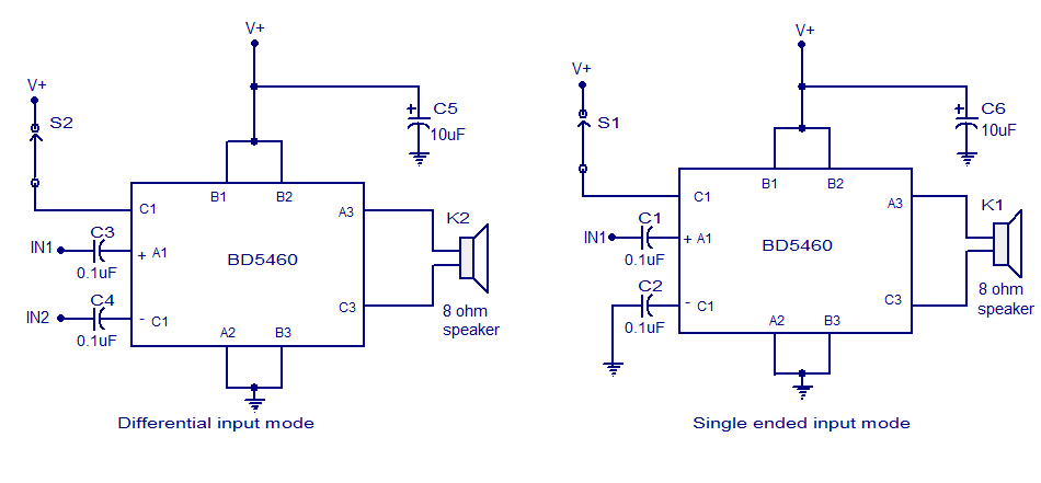
The BD5460 is a low power Class D amplifier that can be utilized in low power applications such as handheld audio devices. The BD5460 does not require an LC filter at the speaker output and can be powered by...
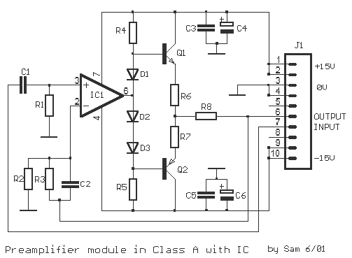
The original description discusses an application that is reputed for its high-quality sound. This superior sound quality is attributed to the operation of the entrance transistors at Class A. The sound quality is largely dependent on IC1, which needs to...
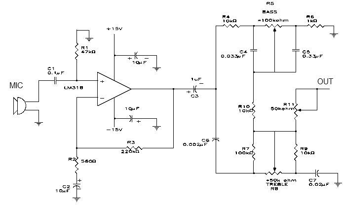
This simple microphone preamplifier is based on the LM318 operational amplifier. The LM318 operates as a standard non-inverting amplifier. Resistor R1 provides a ground input path for the bias current of the non-inverting input. The combination of R2 and...
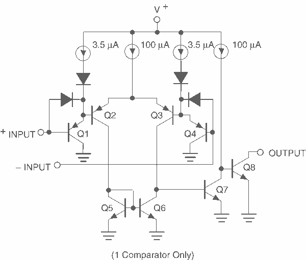
This page provides basic information about voltage comparator integrated circuits and is to act as reference material for other circuits. The circuits shown are based on the LM339 Quad Voltage Comparator chip or the LM393 Dual Voltage Comparator chip....
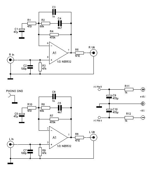
If you still like to spin vinyl and features a turntable, but the amplifier has no more input for a turntable is below a switching solution. We used a NE5532 to a simple stereo RIAA phono preamp to build....
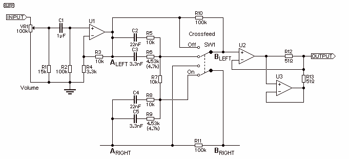
SW1 bypasses the crossfeed network. I have reconfigured the original crossfeed schematic so that now the 100k resistor always bridges the bypass switch and thereby reduces any 'crackle' or 'click' or whatever you may call them. Don't omit these...