Valve Tube Audio/Modulation Amplifiers 15W and 35W
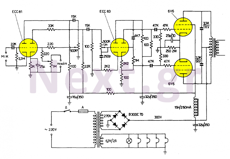
The push-pull power stage is equipped with two EL34 tubes for 35W or 6V6 tubes for 15W. These tubes are powered from the primary output transformer with an 8KΩ impedance. In the secondary, the power coil includes a feedback coil made of approximately 30 turns of 0.3mm wire, with windings for 4Ω or 8Ω loudspeakers, and an additional high impedance winding of 1.25 to 500Ω for long lines and speakers operating at 100V.
These amplifiers can be utilized in the following manner: the 15W amplifier is suitable for a 20-30W transmitter, while the 35W amplifier is appropriate for a 50-70W transmitter. In this configuration, the output transformer of the amplifier/modulator has a transformer ratio of 1:1. The secondary of the 8Ω winding is connected to the secondary of another similar output transformer, with the second primary utilized in the uplink circuit of the transmitter output light.
In their construction, it is recommended to use hard wire connections of 0.6 to 0.8mm with insulation. The wires in the grids should be kept short and distanced from any other instruments or connections that could introduce capacitance. To minimize buzzing at the output from the filaments (due to alternating heating voltage), insulated twisted conductors should be employed to neutralize 50Hz bandwidths.
The circuit design of these amplifiers is characterized by a robust architecture that accommodates various sound input sources while maintaining high fidelity and efficiency. The use of EL34 or 6V6 tubes allows for flexibility in output power, catering to different application requirements. The negative feedback mechanism enhances linearity and reduces distortion, ensuring a clearer audio output. The careful selection of wire gauge and insulation type further contributes to the overall performance by mitigating interference and maintaining signal integrity. Additionally, the design allows for scalability, making it suitable for integration into larger audio systems or transmitters, thereby extending its usability in professional audio applications.These two amplifiers are of very good quality, simple and economical in their manufacture. They have two inputs for a 4mV (500KΩ) sensitivity microphone and an input for any 200mV (1MΩ) sound source, that is, the first input is for speech and the second one for the music. These inputs are set with the potentiometers P1 (the microphone) and P2 (sound source). The P3 potentiometer adjusts the tone of the voice. Watching the amplifier circuit of 30W we see that it uses negative feedback, by phase feedback feedback, a part of the output voltage at the input of the acoustic amplifier.
The push-pull power stage is equipped with two EL34 lamps for 35W or 6V6 for 15W. These lamps are charged from the primary output transformer with an 8KΩ impedance. In the secondary, the power coil includes a feedback coil having about 30 threads of 0.3mm wire, winding 4Ω or 8Ω for the loudspeaker and may also include a high impedance winding of 1.25 ~ 500Ω for the long lines and Speakers operating at 100V.
These amplifiers can be used as follows: The 15W Amplifier for a 20-30W Transmitter and a 35W Amplifier for a 50-70W Transmitter. In this case, the output transformer of the amplifier / modulator has a transformer ratio of 1: 1. The secondary of these 8Ω is connected to the secondary of 8Ω of another output transformer similar to the previous one and the second primary is used in the uplink circuit of the transmitter output light.
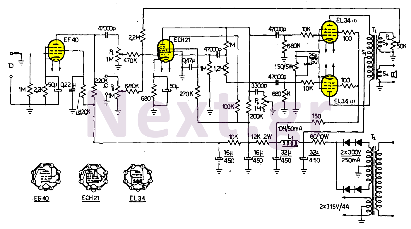
In their construction to use wire connections hard 0.6 + 0.8mm with insulation.
The wires in the grids have a small length and are remote from any other instrument or connection that could create capacity. To reduce the buzzing at the output from the filaments (alternating heating voltage), insulated twisted conductors must be used to neutralize 50Hz bandwidths.
