
Grounded Grid Amplifiers

In a grounded grid amplifier, the design emphasizes the importance of grounding the control grid to minimize RF interference and enhance arc protection. The connection should be implemented with high-quality conductors to ensure minimal resistance and inductance, which can adversely affect performance. The use of multiple pins for grounding reduces the likelihood of ground loops and enhances stability, which is critical in high-power applications.
The series connection of the input and output circuits through the tube facilitates efficient power transfer, as the plate current flows through both the cathode and anode. This arrangement allows for a more straightforward measurement of the plate input power, as the total current can be monitored at various points in the circuit. The historical context provided by FCC regulations underscores the significance of accurately measuring power levels to ensure compliance with operational standards.
The asymmetrical conduction characteristics of the tube are crucial to understanding the relationship between cathode voltage and amplifier output. During negative cathode swings, the tube remains conductive, allowing the RF voltage between the cathode and grid to augment the effective anode-to-cathode voltage. This phenomenon results in an increase in output power without a corresponding increase in the measured voltage, highlighting the need for precise metering techniques to capture the true performance of the amplifier.
Overall, the grounded grid amplifier design requires careful consideration of grounding techniques, circuit layout, and metering practices to achieve optimal performance and compliance with regulatory standards. The interplay between the input and output circuits, as well as the behavior of the tube under varying conditions, forms the foundation for efficient RF amplification in this configuration. Proper understanding and implementation of these principles are essential for engineers and technicians working in the field of RF amplification.Floating the grid above ground is bad for RF, and bad for arc protection. The control grid ground is also the single most critical connection for stability. The grid connection to ground should always be as wide and short as possible, and use as many pins as possible. The input and output circuit of a grounded grid amplifier are connected in series through the tube. Plate current is common through both cathode and anode, and only dc plate voltage is not. Back when we measured power as plate input power and not RF output power, the FCC even had a rule similar to this. The FCC wanted driver plate input power to be included as a full part of power amplifier plate input power.
Thus kilowatt grounded-grid amplifiers, like the Heathkit SB220, when driven by 100-watt exciters could only run 900 watts input if the operator wished to comply with FCC rules. Probably based more on FCC conservatism than actual operation, a few widely accepted handbooks and authorities claim driver power adds to output power via feedthrough and is not accounted for in the metering system.
Thinking unclearly, these books propose full driver power be deducted from output power when calculating efficiency. In actual operation, every single milliampere of anode current contributed by the exciter is fully accounted for in the plate current metering.
The only thing not accounted for is a portion of the average cathode-to-grid voltage, which directly adds to the anode-cathode voltage during negative cathode swings. During positive cathode voltage excursions the gird is more negative compared to the cathode, so the tube cuts off.
Since the tube is just "coasting" the positive cathode swing does not detract from effective operating anode voltage. This asymmetrical tube conduction causes the RF voltage between cathode and grid to contribute to amplifier output by adding effective anode-to-cathode voltage without the additional voltage showing on meters.
If we look at this circuit we can see what that happens, because the anode and cathode are indeed in series! As in all series circuits, current is the same at all points in a mesh or loop. We only have to insert an anode current meter in the anode or in the negative rail of the HV supply to measure the full effect of drive power on plate input power.
The metering shortfall is confined to measuring effective anode-to-cathode voltage, since the meter connects from HV to ground (to the grid, not to the cathode). The meter also cannot read the time-varying cathode voltage accurately because it is the wrong type of meter (it can`t read average voltage) and it is connected across the wrong two points.
HV is read from grid to anode, while the signal source is in series with the HV supply, adding grid-cathode RF voltage to effective high voltage on negative swings of the cathode. Since the tube conducts heavily during negative cathode swings, that is also when the extra voltage provides the largest contribution to output power.
With the output and input in series, a grounded grid amplifier 🔗 External reference
Related Circuits
The first choice is usually an integrated circuit designed for the purpose. A typical assortment can be seen on this National Semiconductor page. Discrete designs can also be built with readily available transistors or op-amps, and many designs are...

The 60 Watt linear amplifier is a straightforward all-solid-state circuit utilizing the power MOSFET IRF840. The IRF series of power transistors are available in various voltage and power ratings. A single IRF840 can handle a maximum power output of...
While conversing with a distant subscriber on the telephone, it is common to experience frustration due to faint audio that is barely intelligible. To address this issue, an inexpensive amplifier circuit is proposed. This circuit can be easily assembled...
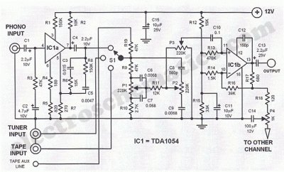
This Hi-Fi stereo preamplifier circuit is constructed using the TDA1054 integrated circuit (IC) from SGS. The TDA1054 is housed in a 16-pin DIL package and incorporates two separate preamplifier circuits. It is characterized by low noise and minimal issues...
The description refers to three circuits of the Recording Industry Association of America (RIAA), which are designed for the amplification of low signals from Moving Magnet (MM) heads. These circuits follow different solutions, each one concerning the equalization (eq). In...
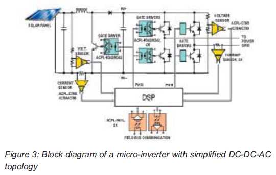
Both help improve efficiency and protect micro-inverters in photovoltaic (PV) solar applications. In 2009, the residential solar photovoltaic (PV) inverter market represented 90 percent of the total PV. The integration of micro-inverters in photovoltaic solar applications has significantly enhanced system...