
Variable (Adjustable) Current Limiter Circuit
The automatic current limiting circuit described operates on the principle of feedback control to prevent excessive current flow, thus protecting both the circuit and the load. The operational mechanism involves the use of a current sensing resistor (R1), which generates a voltage proportional to the current flowing through it. This voltage is monitored by the transistor Q2, which acts as a switch that responds to the sensed current.
The potentiometer R2 allows for fine-tuning of the current limit. By adjusting its resistance, the user can set the desired threshold at which the circuit will begin to limit the current. When the load current exceeds the set limit, the voltage across R1 increases, causing Q2 to conduct. This conduction effectively pulls the base voltage of transistor Q4 to ground, reducing its output to the load and thereby limiting the current.
The circuit is designed to handle a range of input voltages, with the 2N3055 transistor providing sufficient power dissipation capacity. The transistor must be adequately heat-sinked to manage the thermal load generated during operation, especially at high current limits. The circuit's ability to handle a maximum voltage of 60 V, while maintaining a current limit of 1.9 A, showcases its versatility in various applications where current regulation is critical.
In summary, this automatic current limiting circuit is a robust solution for applications requiring precise current control, offering adjustable limits and high voltage handling capabilities while ensuring the safety and longevity of both the circuit and connected components.This circuit provide automatic current limiting up to 8. 4A. Unlike current limiter that uses only a resistor, this current limiting circuit doesn`t drop the voltage, or at least keep the voltage drop at minimum, until a certain current amount is exceeded. This current amount limit is adjustable from 1. 4 A to 8. 4A using a potentiometer. You can mod ify the component value to give different current limiting range. Here is the circuit`s schematic diagram: The resistor R1 is there to sense the current. At R2 potentiometer at minimum resistance (the center tap connected to R1), if the current drawn by the load reach 1. 2A then the voltage across R1 reach 0. 6V and Q2 begin conducting, thus shorting the base voltage of Q4 to ground. This shorting action reduce the base current and therefore reduce the output voltage sensed by the load, and prevent the current to flow further.
If you need the current limiter to limit at lower threshold range, you can change the R1 to 1R and you`ll get about 0. 7A to 4. 2A adjustment range. Because of the power dissipation capability of 2N3055 transistor, at the worst case that the load is shorted to ground (zero resistance), if you limit the current to 8.
4 A then the circuit can handle maximum source voltage of 14V, while limiting the current at 4. 2A can handle up to 27V source voltage. The maximum voltage can be handled by this circuit is 60 volt, but at that maximum voltage you can only safely set the current limit at 1. 9A in the extreme condition, when the load is shorted to ground. Please make sure the Q1 transistor has sufficient heat sink. [Circuit Schematic Source: Designed by FreeCircuitDiagram. Com] 🔗 External reference
Related Circuits
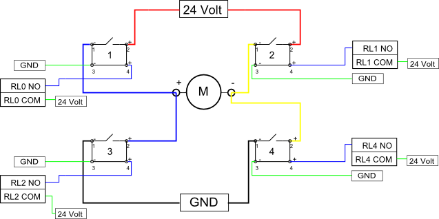
Eight solid-state relays (SSR) and an ADAM-4068 (Serial-I/O device) are utilized to wire a circuit for controlling a motor in a robotic application. The ADAM-6048 is a versatile device that facilitates control of digital inputs and outputs via RS-485...
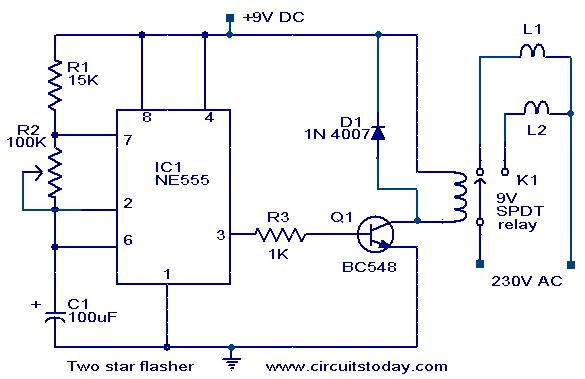
A circuit designed to alternately flash two Christmas stars is presented. The NE555 integrated circuit (IC1) is configured as an astable multivibrator. When IC1 outputs a positive pulse, transistor Q1 becomes conductive, activating relay K1. Consequently, lamp L2, connected...

This circuit is based on the Sharp GP1U52X infrared module and the 1NS8048L microprocessor. The GP1U52X is a hybrid integrated circuit and infrared detector that provides a strong, clean signal for subsequent filtering and demodulation. The circuit utilizes the Sharp...
This document details the AT Keyboard Interface and AT Keyboard Protocols. It includes an example of a Keyboard to ASCII decoder utilizing a 68HC705J1A microcontroller. The AT Keyboard Interface is a standard communication protocol used primarily in personal computers to...

The system employs an optical fingerprint sensor utilizing the ARM Cortex M3 core, specifically the STMicroelectronics 32-bit high-performance microcontroller STM32F205RE. It incorporates a function body composition that utilizes the Sobel edge detection operator, Gabor filtering, image binarization, and various...
This circuit diagram illustrates a light-activated switch utilizing the National Semiconductor comparator IC LM311 and a light-dependent resistor (LDR). The configuration is based on a voltage comparator circuit centered around IC1. The non-inverting input of IC1 receives a reference...