
Light Activated Day Night Switch Circuit
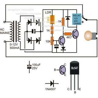
The circuit operates based on the principle of light intensity detection using an LDR, which changes its resistance depending on the amount of light it receives. The LM311 comparator plays a critical role in comparing the reference voltage with the voltage derived from the LDR. The reference voltage is established through a voltage divider formed by resistors R3 and R4, ensuring that the non-inverting input maintains a steady 6V under varying conditions.
When the ambient light level is low, the high resistance of the LDR results in a voltage drop that keeps the inverting input above the reference voltage. The output of the LM311 remains low, signaling that the relay should remain off. In contrast, as the light intensity increases, the resistance of the LDR decreases, leading to a drop in voltage at the inverting input. Once this voltage falls below the 6V reference, the comparator's output transitions to a high state, providing sufficient voltage to turn on transistor Q1.
Transistor Q1 acts as a switch that controls the relay. When activated, the relay can be used to control various loads, such as lights or alarms, providing a practical application for the circuit in automatic lighting systems or security devices. The inclusion of the adjustable potentiometer R1 allows for fine-tuning of the sensitivity of the circuit, enabling users to set the threshold at which the relay activates based on ambient light conditions. This feature enhances the versatility of the circuit in different environments and applications.This is the circuit diagram of a light activated switch based on National Semiconductors comparator IC LM 311 and a LDR. The circuit is based on a voltage comparator circuit wired around IC 1. The non inverting in put of IC1 is given with a reference voltage of 6V using resistors R3 and R4. The input to the inverting input will be the voltage acros s the LDR that is light dependent. At darkness the resistance of the LDR will be high and so do the voltage across it. At this condition the voltage at the inverting input will be higher than the reference at non inverting pin and the out put of the comparator will be low(~o V). When the LDR is illuminated, its resistance drops and so do the voltage across it. Now the voltage at inverting input will be lower than that at non inverting input and the out put of the comparator goes high (~12 V).
This makes transistor Q1 on and it drives the relay. As a result we get a relay switching according to the intensity of the light falling on the LDR. Adjust POT R1 to set the desired light intensity for switching the relay. For this illuminate the LDR with the desire intensity light. The relay will be either on or off. Adjust POT R1 slowly so that the state of the relay changes. That`s it. Now the circuit is set for the given intensity of light. 🔗 External reference
Related Circuits
The use of diode rectifiers in AC voltmeters with a low lower limit of measurement range (0.5-1 V) leads to significant nonlinearity of the scale due to the nonlinearity of the current-voltage characteristics of diodes. The incorporation of electronic...

The EMR 4.0 operates with a single power supply ranging from 6V to 10V, with an optimal supply voltage of 9V. It requires effective power filtering to minimize noise, particularly when there is no signal input. The quiescent current...
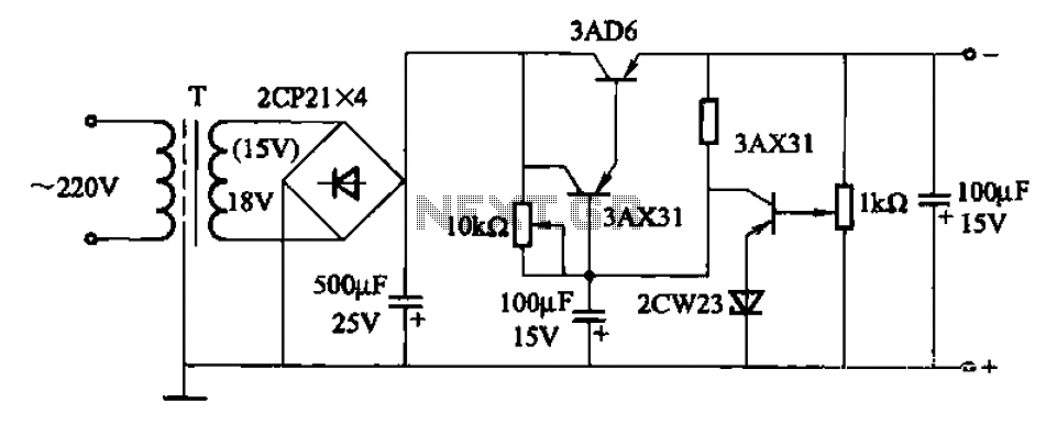
A power supply circuit designed to operate within a voltage range of 6 to 15V, providing a current output of 500mA. This circuit includes an adjustable amplification segment and utilizes a composite transistor configuration for its power supply. The described...
The circuit utilizes a 555 timer integrated circuit (IC) configured as an astable multivibrator. The flashing rate can be adjusted from very fast to a maximum of once every 1.5 seconds by changing the setting of the preset variable...
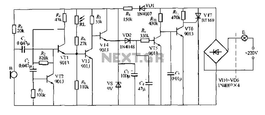
This circuit design is a sound and light control delay switch for staircase walkway lighting, featuring high voice sensitivity. In the evening, when someone walks on the stairs, their footsteps activate the electronic meter, turning on the lights. If...
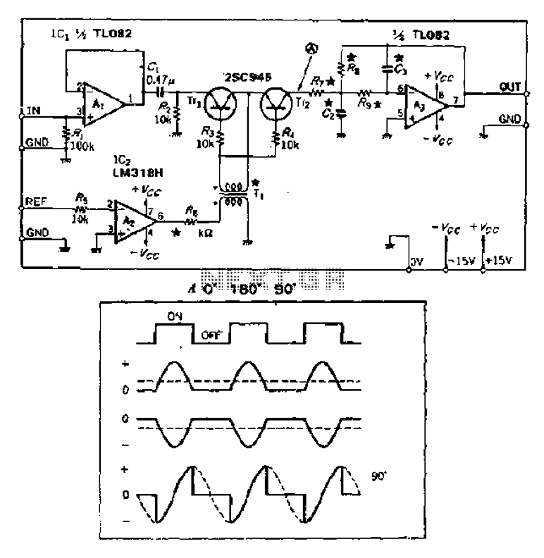
Analog switches alternately pass and block the input signal through a low-pass filter to create a pulsating flow smoothing effect, converting it into a direct current (DC) signal. The operational amplifier, referred to as OP Xiao Ai, functions as...