
Variable Frequency And Duty Cycle Oscillator
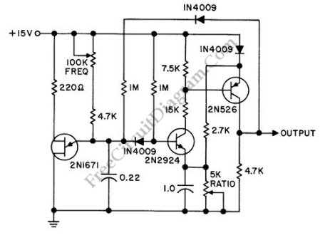
The discrete oscillator circuit is designed to produce oscillations with adjustable frequency and duty cycle, making it versatile for various applications. The core of the circuit typically includes components such as resistors, capacitors, and transistors or operational amplifiers configured to create feedback loops that sustain oscillation.
The frequency of oscillation can be altered by varying the values of the resistors and capacitors in the timing network. For instance, increasing the capacitance or resistance will generally lower the frequency, while decreasing these values will raise the frequency. The duty cycle, which defines the proportion of one cycle in which the output is active, can also be adjusted by modifying the charge and discharge paths of the timing capacitor.
In practical applications, this type of oscillator can be used in signal generation for audio applications, clock pulses for digital circuits, or modulation signals in communication systems. The output waveform can be a square wave, triangle wave, or sawtooth wave, depending on the specific configuration of the circuit components and the desired application.
To ensure stability and performance, it is crucial to select components with appropriate tolerances and characteristics, especially in high-frequency applications where parasitic capacitance and inductance can significantly affect circuit behavior. Additionally, power supply decoupling may be necessary to maintain consistent performance under varying load conditions.
Overall, the discrete oscillator circuit offers a flexible solution for generating variable frequency and duty cycle signals suitable for a wide range of electronic applications.A discrete oscillator circuit shown in the schematic diagram below is? a variable duty cycle and variable frequency oscillator, can be used to produce. 🔗 External reference
Related Circuits
This is a classic frequency divider by two, implemented using a T-flip flop circuit, specifically with IC1 [4011]. In this circuit, the frequency from the network, after limiting the negative half-period of the sine wave and transforming it into...
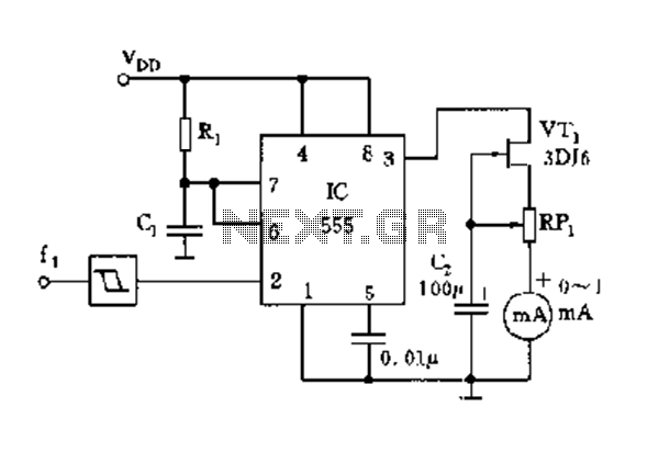
The circuit consists of a 555 timer along with components R1, C1, and other elements configured as a monostable delay circuit. The input square wave signal is shaped by a Schmitt trigger to meet the triggering requirements. The 555 timer...

This circuit is designed for an RF (radio frequency) transmitter experiment, where a watt meter is instrumental in optimizing the transmitter circuit. A simple RF watt meter circuit is illustrated in the schematic diagram below. The circuit is not...
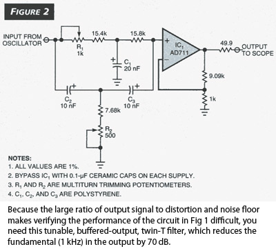
The Wien-bridge sine-wave oscillator utilizes a light bulb for amplitude stabilization. The circuit depicted in Fig 1 omits the light bulb and incorporates several enhancements that reduce distortion and produce a test signal sufficiently pure for evaluating modern operational...
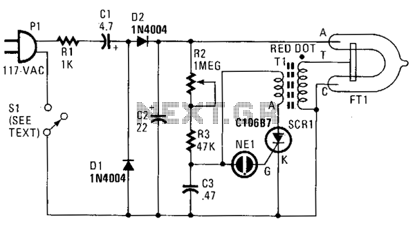
In this strobe light, two circuits are required: one circuit charges a capacitor to create a 320 V DC potential between the cathode and anode of the flashtube, while the other circuit generates bursts of approximately 4000 V to...
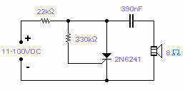
Silicon controlled rectifiers (SCR) can easily oscillate if there is an inductor (a speaker coil in this case) which gives just enough extra voltage to completely switch off the sustain current. In this way a new cycle may start...